Apparatus for controlling a power using a smart device and method thereof

a smart device and power control technology, applied in the direction of mechanical power/torque control, resistance welding apparatus, ratio control, etc., can solve the problems of inability to offer such an inducement, inability to provide real-time information on electricity/power charges, and manual recovery of power, so as to achieve energy saving and reduce power consumption of these devices

Active Publication Date: 2011-08-11
LG ELECTRONICS INC
View PDF23 Cites 231 Cited by
  • Summary
  • Abstract
  • Description
  • Claims
  • Application Information

AI Technical Summary

Benefits of technology

[0035]First of all, according to one embodiment of the present invention, environments in using indoor devices (e.g., home appliances) are optimized, whereby power consumption by these devices can be reduced.
[0036]According to another embodiment of the present invention, it is unnecessary for a user to manually control or monitor home appliances one by one, whereby a user's needs can be met.
[0037]According to another embodiment of the present invention, a method of recycling green energy and providing energy conservation can be provided.
[0038]According to another embodiment of the present invention, problems or limitations of conventional data protocols are addressed and the conventional data protocols can be configured to provide an interactive power control system.
[0039]According to another embodiment of the present invention, a power saving function which relies on power / electric rates information (e.g., information on electricity rates, etc.) and a user's command for manual manipulation can be effectively provided.

Problems solved by technology

When a problem occurs, the power has to be manually recovered.
Further, real-time information on the electricity / power charges is not provided.
Therefore, it is unable to offer such an inducement as an incentive to a user through price variation.

Method used


Image

  • Apparatus for controlling a power using a smart device and method thereof
  • Apparatus for controlling a power using a smart device and method thereof
  • Apparatus for controlling a power using a smart device and method thereof

Examples


Embodiment Construction

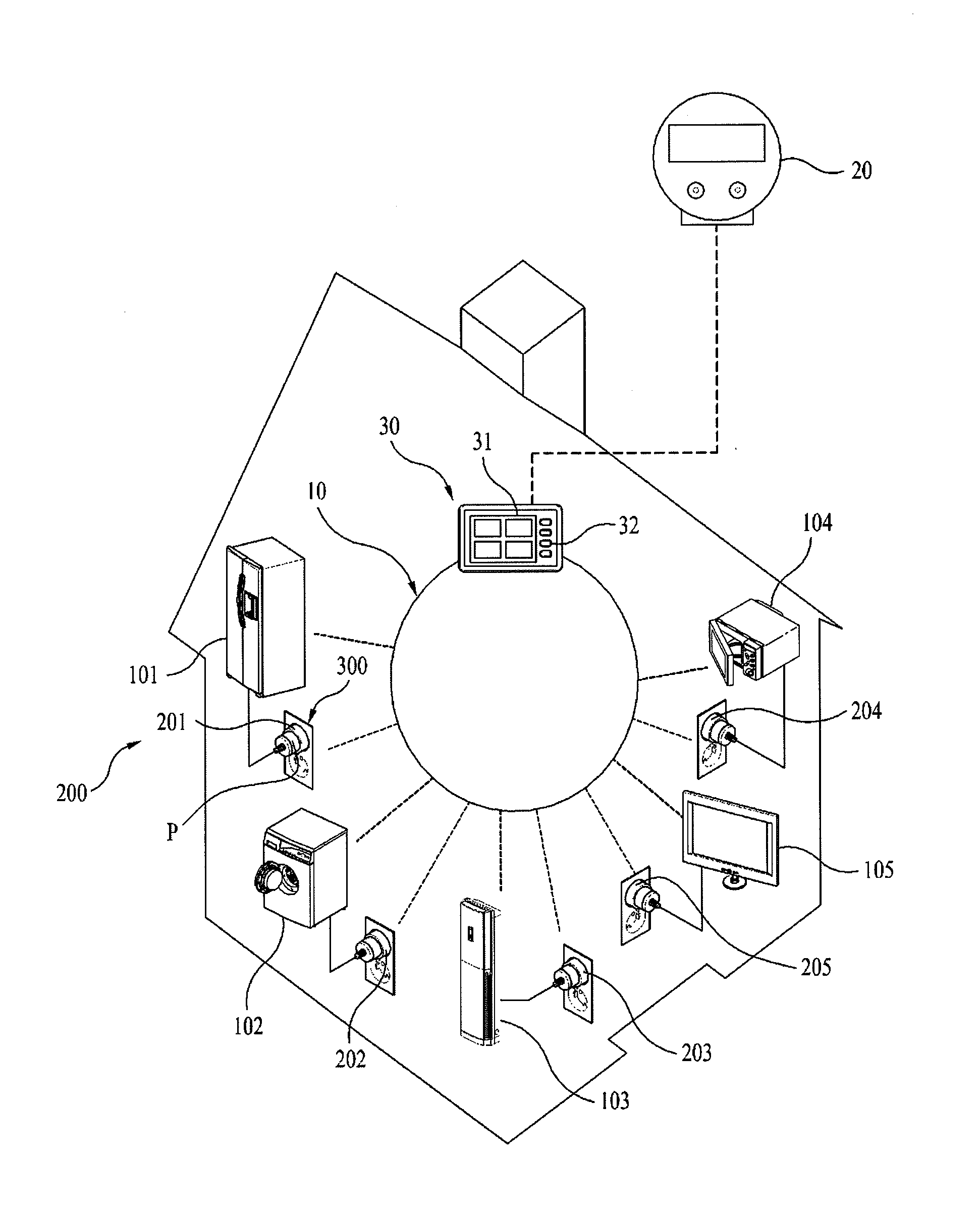
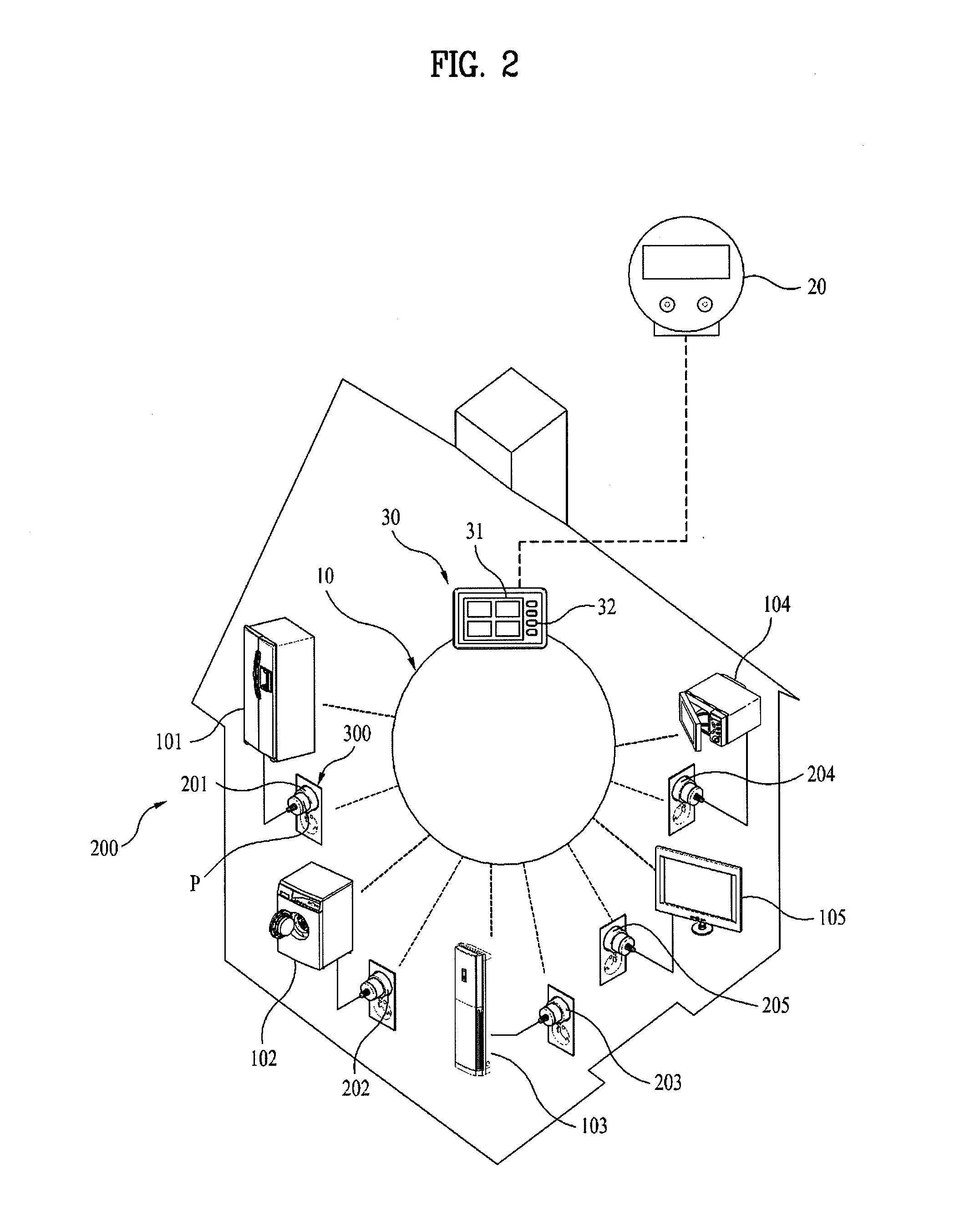
[0098]Reference will now be made in detail to the preferred embodiments of the present invention, examples of which are illustrated in the accompanying drawings. First of all, terminologies or words used in this specification and claims are not construed as limited to the general or dictionary meanings and should be construed as the meanings and concepts matching the technical idea of the present invention based on the principle that an inventor is able to appropriately define the concepts of the terminologies to describe the inventor's invention in best way. The embodiments disclosed in this disclosure and configurations shown in the accompanying drawings are just preferred embodiments and do not represent all technical ideas of the present invention. Therefore, it is understood that terminologies not disclosed in this specification can be construed as the following meanings and concepts matching the technical ideas of the present invention. In the present invention, the term ‘powe...


PUM

PropertyMeasurementUnit
temperatureaaaaaaaaaa
setting temperatureaaaaaaaaaa

Abstract

A smart device is discussed, which is connected to a smart grid to perform a power saving function. According to an embodiment, the smart device includes a power information receiving unit configured to receive power information through the smart grid network; a power saving control unit configured to perform the power saving function for at least one apparatus based on the power information in a power saving mode; at least one mode switching unit configured to switch from the power saving mode to a manual mode according to a user command; and a manual mode operational time determining unit configured to determine a manual mode operational time for operating the at least one apparatus in the manual mode, the at least one mode switching unit further configured to switch from the manual mode back to the power saving mode, automatically, when the manual mode operational time expires.

Description

[0001]Pursuant to 35 U.S.C. §119(a), this application claims the benefit of earlier filing date and right of priority to Korean Application No. 10-200X-XXXXXXX, filed on MMMM DD, 20XX, the contents of which are hereby incorporated by reference herein in their entirety.BACKGROUND OF THE INVENTION[0002]1. Field of the Invention[0003]The present invention relates to an automatic power controlling technology, and more particularly, to a smart server and a method of controlling power used by a device using the same.[0004]2. Discussion of the Related Art[0005]Generally, power for operating an electric / electronic appliance such as a home appliance used at home, an office device used at office and the like is supplied in order of a power plant operated by a public facility or a private organization, transmission lines and wiring lines. This is characterized as a central power source instead of a distributed power source, and has a radial structure expanding from a center to a periphery, and...

Claims


Application Information

Patent Timeline
Patent Type & Authority Applications(United States)
IPC IPC(8): G06F1/32
CPCG06Q50/06Y04S20/242H04L12/10H04L69/04H02J3/14H02J7/35H02J2003/143H02J2003/146Y02B70/3225Y02B70/3233Y02B70/3266Y04S20/222Y04S20/224Y04S20/225H02J9/005H04L12/12H02J2310/64H02J2310/14H02J2310/16Y02B70/30Y02D30/50Y04S20/20Y04S50/10
Inventor PARK, JONG SOOSONG, JONG HWAPAIK, WOO HYUN
Owner LG ELECTRONICS INC
Why Eureka
Try Eureka