Shoe sole suitable for suppressing pronation

a technology of pronation suppression and shoe sole, which is applied in the field of shoe soles, can solve the problems of insufficient suppression of pronation and likely wrong fixing positions, and achieve the effect of reducing the wear resistance of the peripheral portion, reducing the wear resistance, and being easy to wear away

Active Publication Date: 2011-08-18
ASICS CORP
View PDF9 Cites 80 Cited by
  • Summary
  • Abstract
  • Description
  • Claims
  • Application Information

AI Technical Summary

Benefits of technology

[0059]In this embodiment, one can enjoy the appearance of the hard member of a chromatic color, and carbon black used in the frame portion as a reinforcing filler increases the wear resistance of the peripheral portion which is easily worn away.
[0060]

Problems solved by technology

Integrating each protrusion, one by one, with the wave-shaped plate is time-consuming, and the fixin

Method used


Image

  • Shoe sole suitable for suppressing pronation
  • Shoe sole suitable for suppressing pronation
  • Shoe sole suitable for suppressing pronation

Examples


embodiment 1

[0115]FIGS. 1 to 13 show Embodiment 1.

[0116]General Configuration:

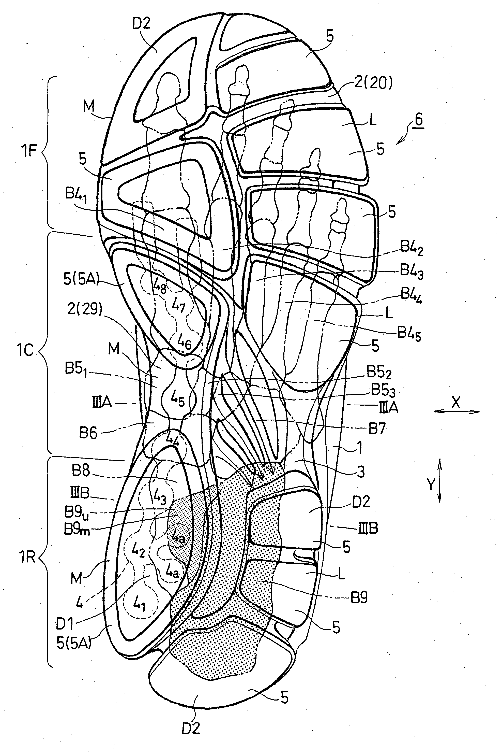
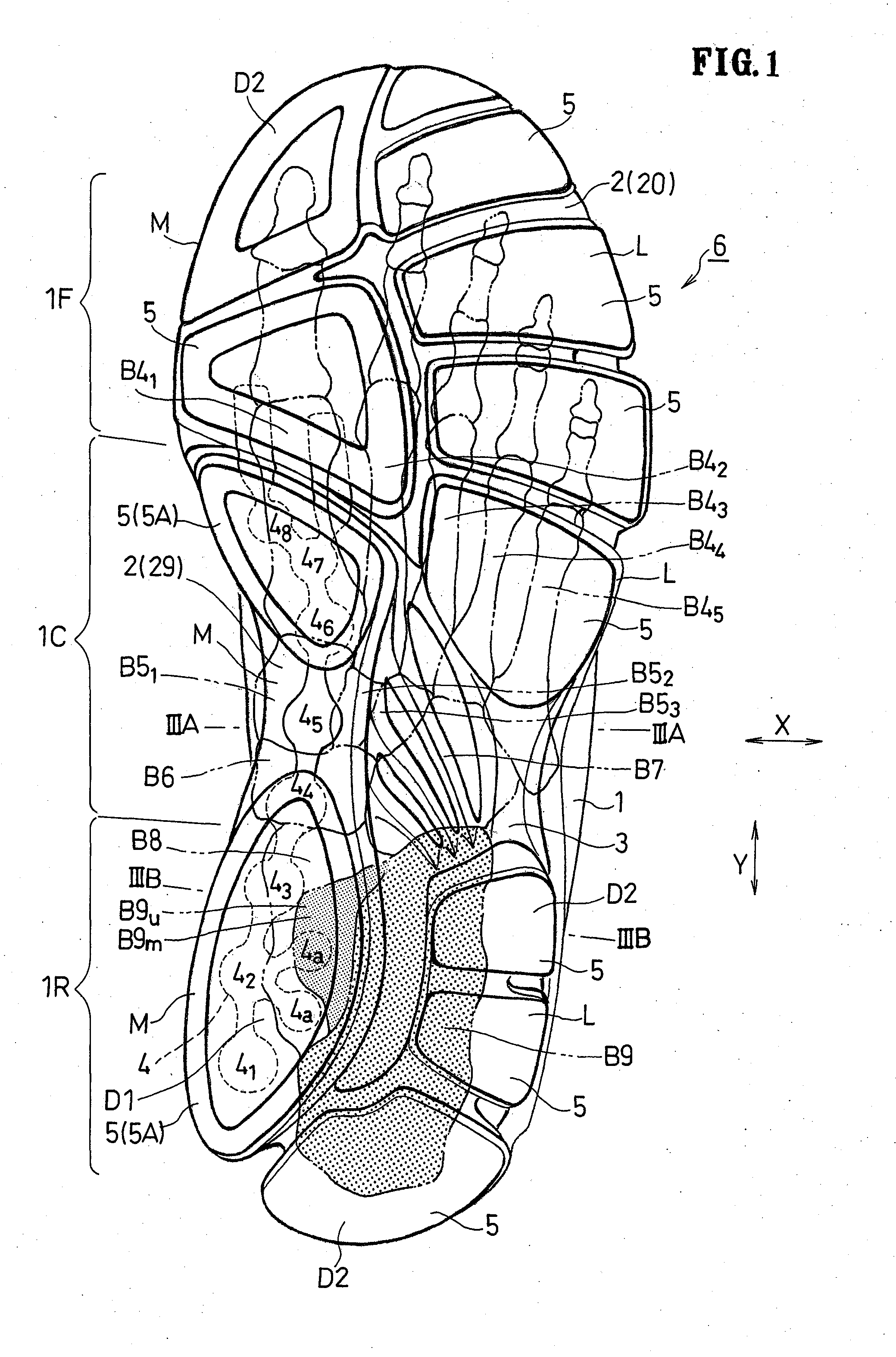
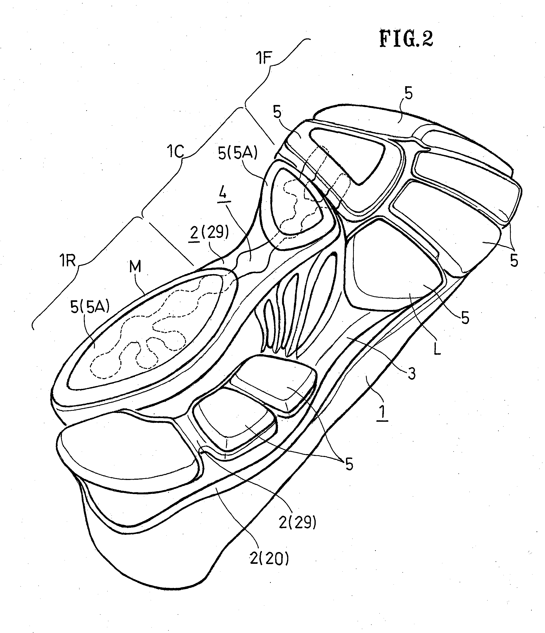
[0117]In FIGS. 10 and 11, a shoe with a shoe sole 6 of the present invention includes an upper 1 that wraps around the instep, a midsole 2, a heel cup (an example of the resin plate) 3, an outsole 5, etc. The shoe sole 6 includes a front foot portion 1F, a middle foot portion 1C and a rear foot portion 1R provided continuous with one another in the front-rear direction Y of the foot.

[0118]In the present embodiment, the “front foot portion” is understood as being a portion of the foot in front of the head of the metatarsal bone B4i shown in FIG. 1, for example, not including the arch. The “middle foot portion” refers to a portion placed between the front foot portion and the rear foot portion, including the shaft and the base of the metatarsal bone B4i, the cuneiform bone B5i, the navicular bone B6 and the cuboid bone B7, for example. The “rear foot portion” refers to a portion including the heel of the foot, e.g., the...

embodiment 2

[0166]FIGS. 14A and 14B show Embodiment 2.

[0167]In the present embodiment, above the embedded portion 4i, the upper surface 2u of a midsole body 20A and a slope surface 4s of the embedded portions 4i are generally parallel to each other.

[0168]More preferably, the angle 01 of the slope surface 4s with respect to the horizontal line HL is greater than the angle θ2 of the upper surface 2u of the midsole with respect to the horizontal line HL. With such settings, the thickness of the midsole body 20A does not increase toward the edge on the medial side M above the embedded portions 4i. Therefore, the foot less easily leans on the medial side.

[0169]Note that the heel cup is absent in Embodiment 2.

[0170]The other configuration is similar to that of Embodiment 1, like components are denoted by like reference numerals and will not be described below.

[0171]Next, an example of the structure of the embedded portions 4i and the holes 2i will be described.

[0172]FIGS. 15A and 15B schematically sh...


PUM


Abstract

Three or more holes are formed in a lower portion of a first area D1 in a midsole body 29 separated from one another in a front-rear direction Y, each hole opened in a downward direction and having an inner peripheral surface about an axial line extending in an up-down direction; embedded portions each have an outer peripheral surface about the axial line, and are embedded in the midsole body 29 while being fitted into the holes; the embedded portions are formed by a hard member 4 made of a resin harder than midsole bodies 20 and 29 and outsoles 5 and 5A; and the hard member 4 includes a connecting portion for connecting together the embedded portions in the front-rear direction Y on the lower surface of the midsole body 29.

Description

TECHNICAL FIELD[0001]The present invention relates to a shoe sole suitable for suppressing pronation.BACKGROUND ART[0002]When running, each foot lands on the lateral side of the heel and then the center of the load moves to the medial side of the front foot portion. In this process, the heel pronates. Suppressing excessive pronation serves to prevent leg injuries due to running.[0003]U.S. Pat. No. 6,199,302 discloses a shoe sole in which the medial side of the middle foot portion and the rear foot portion of the midsole is formed by a harder material than other portions of the midsole.[0004][First Patent Document] U.S. Pat. No. 6,199,302 (FIG. 1)DISCLOSURE OF THE INVENTION[0005]However, with a midsole of a higher hardness and a midsole of a lower hardness, there is an abrupt hardness difference at the boundary therebetween. Therefore, the wearer may feel an upthrust on the foot sole (plantar surface) at the boundary.[0006]Japanese Laid-Open Patent Publication No. 2004-242692 disclos...

Claims


Application Information

Patent Timeline
IPC IPC(8): A43B13/18
CPCA43B7/24A43B13/125A43B13/186
Inventor NISHIWAKI, TSUYOSHINAKAYA, SEIGOMORIYASU, KENTAKUROSAKI, KIYOMITSU
Owner ASICS CORP
Why Eureka
Try Eureka