
Biological component-measuring device and method for calibrating the same

Active Publication Date: 2011-08-18
NIKKISO COMPANY
View PDF44 Cites 24 Cited by
  • Summary
  • Abstract
  • Description
  • Claims
  • Application Information

AI Technical Summary

Benefits of technology

[0010]An objective of the present invention is to provide a biological component-measuring device which is capable of removing the problems as described above and measuring biological components accurately, and the whole of which can be calibrated easily and thoroughly. Another objective of the present invention is to provide a biological component-measuring device, various channels of which can be exchanged hygienically and easily, and which is still capable of measuring biological components. A further objective of the present invention is to provide a safe, reliable and easy method for calibrating a biological component-measuring device.
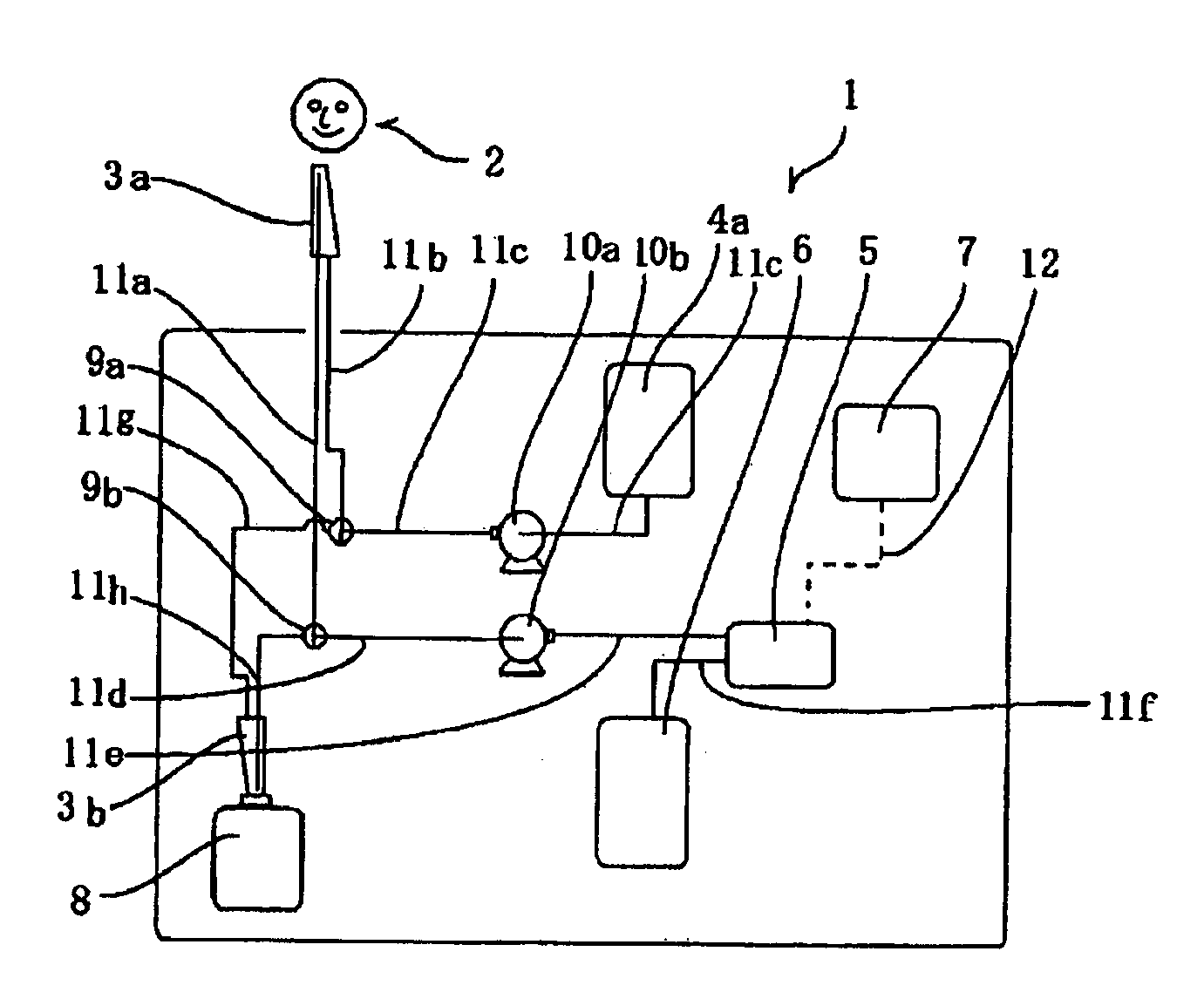
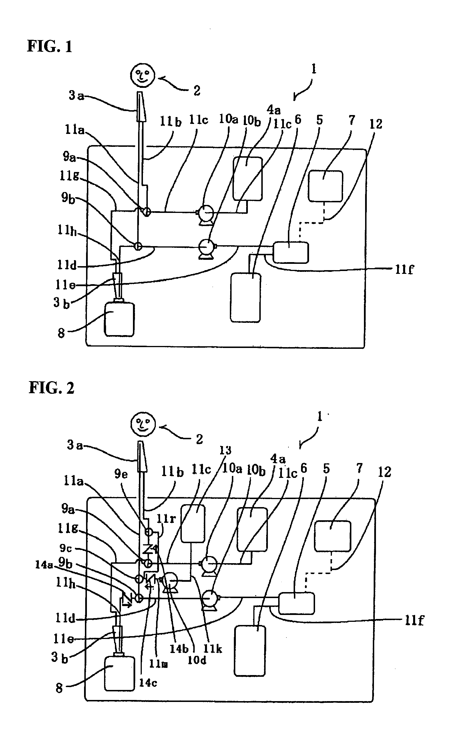
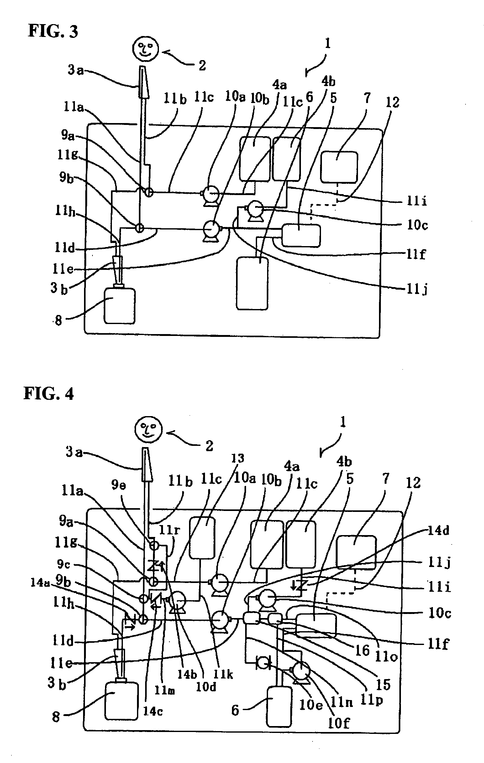
[0065]The calibration method of the present invention includes the operational step of introducing a flushing liquid into the sample channel at a flow rate larger than the flow rate of the sample, which is called “the first step”, during a measurement of a biological component. The introduced flushing liquid cleans elements such as the sample channel, the body fluid sampler and the sensor, and discharges undesired matters such as clots and gelled body fluid as well as the sample from the biological component-measuring device. When the flushing liquid does not include the component being measured, a zero point calibration can be carried out even under the condition where the body fluid sampler is connected to the human body. The method also includes the operational step of introducing a calibrating liquid into the sensor by switching the first flow path changeover valve placed in the sample channel so that the passing of the calibrating liquid is selected, after the first portion of the flushing liquid is introduced into the sample channel and the sensor, which is called “the second step”. The use of a calibrating liquid including a particular component being measured enables the sensor to measure the component in known concentrations and to output corresponding measured values. The operator is able to calibrate the biological component-measuring device as a whole, preparing a working curve based on these measured values and the value obtained in the first step. The method further includes the operational step of introducing a second portion of the flushing liquid at a flow rate smaller than the first flow rate into the sample channel at a location upstream of the first flow path changeover valve and into the body fluid sampler during the second step, which is called “the third step”. The third step serves to prevent the body fluid such as blood from clotting in the sample channel between the body fluid sampler and the first flow path changeover valve during the calibrating operations.

Problems solved by technology

However, calibration of only the sensors of a biological component-measuring device sometimes is not sufficient to provide accurate measurement because of aging of or variation with time in other units and members of the device.

Method used


Image

  • Biological component-measuring device and method for calibrating the same
  • Biological component-measuring device and method for calibrating the same
  • Biological component-measuring device and method for calibrating the same

Examples


Embodiment Construction

1. THE REFERENCE NUMERALS

[0078]1 . . . biological component-measuring device; 2 . . . examinee; 3a . . . body fluid sampler; 3b . . . calibrating liquid sucker; 4a. . . body fluid-diluting liquid tank; 4b . . . diluent tank; 5 . . . sensor; 6 . . . waste liquid tank; 7 . . . sensor signal processor; 8 . . . calibrating liquid tank; 9a . . . second flow path changeover valve; 9b . . . first flow path changeover valve; 9c, 9d, 9e . . . third, fourth and fifth flow path changeover valves; 10 . . . pump tube; 10a, 10b, 10c, 10d, 10e, 10f . . . pump; 11a . . . first portion of a sample channel; 11b . . . second portion of a body fluid-diluting liquid channel; 11c . . . third portion of the body fluid-diluting liquid channel; 11d . . . second portion of the sample channel, 11e . . . third portion of the sample channel; 11f . . . waste liquid channel; 11g . . . second body fluid-diluting liquid channel; 11h . . . calibrating liquid channel; 11i . . . first portion of a first diluent channe...


PUM

PropertyMeasurementUnit
Concentrationaaaaaaaaaa
Levelaaaaaaaaaa

Abstract

This invention provides a biological component-measuring device, enabling the operator to easily calibrate the entire device and capable of measuring biological components accurately, and a method for calibrating the device. The device measures a sample including a body fluid taken through a body fluid sampler by sending it with a pump through a sample channel to a sensor. The device further includes a calibrating liquid channel through which a calibrating liquid can be supplied to the sensor via the sample channel by a switching of a first flow path changeover valve placed in the sample channel at a location upstream of the pump and connected to the channel. The method includes introducing the calibrating liquid in the calibrating liquid channel, via other channels, into the sensor by switching the valve.

Description

CROSS-REFERENCE TO PRIOR RELATED APPLICATIONS[0001]This is a U.S. National Phase Application under 35 U.S.C. §371 of International Patent Application No. PCT / JP2007 / 000466 filed Apr. 26, 2007 which claims the benefit of Japanese Application No. 2006-122469 filed Apr. 26, 2006 both of which are incorporated by reference herein in their entireties.BACKGROUND OF THE INVENTION[0002]1. Field of the Invention[0003]The present invention relates to a biological component-measuring device and a method for calibrating a biological component-measuring device. More particularly, the present invention relates to a hygienic biological component-measuring device that is used for medical support devices and devices of this kind, which biological component-measuring device enables the operator to easily calibrate the entire device as well as the sensors thereof, and to attach a channel-carrying substrate to the device easily, which improves operability. The present invention also relates to a method...

Claims


Application Information

Patent Timeline
IPC IPC(8): G01N27/416
CPCA61B5/1486G01N35/00693G01N27/3274A61B5/1495
Inventor MURAKAMI, MOTOAKI
Owner NIKKISO COMPANY
Learn More