Light Source Unit, Optical Scanning Display, and Retinal Scanning Display

a technology of light source unit and optical scanning display, which is applied in the direction of lighting and heating apparatus, instruments, mechanical equipment, etc., can solve the problems of unavoidable increase in size and cost of light source unit, inability to detect abnormal light intensity due to failure of photodiodes b>700/b>, and inability to detect abnormal light intensity due to failure of photodiodes, etc., to achieve suppress power consumption and heat generation, and reliably detect abnormal light intensity

Inactive Publication Date: 2011-08-18
BROTHER KOGYO KK
View PDF2 Cites 36 Cited by
  • Summary
  • Abstract
  • Description
  • Claims
  • Application Information

AI Technical Summary

Benefits of technology

[0020]An aspect of the disclosure is to provide a light source unit capable of more reliably detecting an abnormal intensity of emitted light while suppressing the power consumption and the heat generation without causing a loss of the light intensity, and to provide an optical scanning display and a retinal scanning display, each display including the light source unit.

Problems solved by technology

However, if an abnormality occurs in intensity of any of the lights emitted from the light sources 500R, 500G, and 500B, the intensity of the light entering the eye 600 of the user may be excessively increased.
Further, as a matter of course, an abnormality of the light intensity due to a failure of the photodiode 700 cannot be detected.
An increase in size and cost of the light source unit is hence unavoidable.
Consequently, power consumption and heat generation are increased.

Method used


Image

  • Light Source Unit, Optical Scanning Display, and Retinal Scanning Display
  • Light Source Unit, Optical Scanning Display, and Retinal Scanning Display
  • Light Source Unit, Optical Scanning Display, and Retinal Scanning Display

Examples


Embodiment Construction

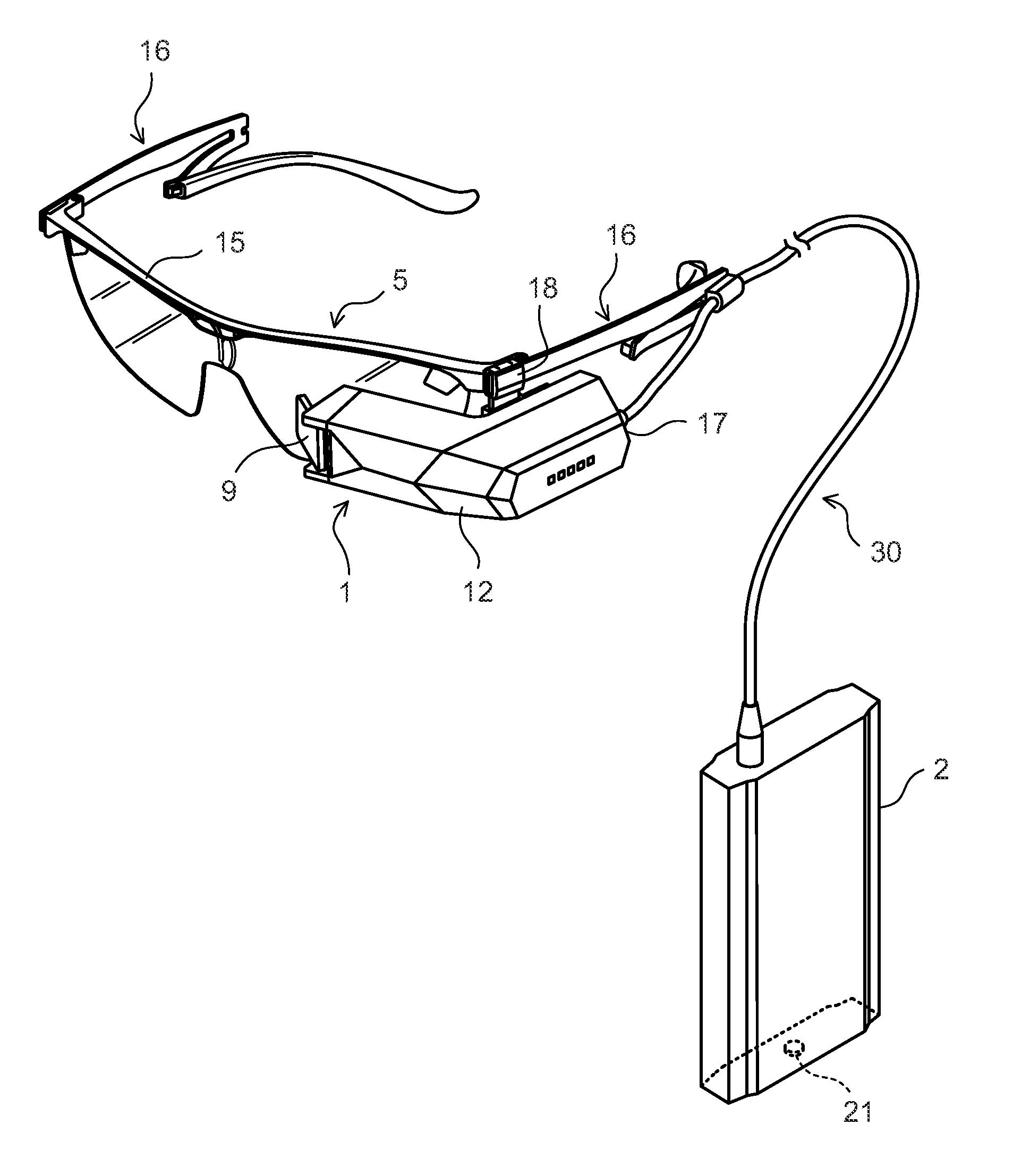
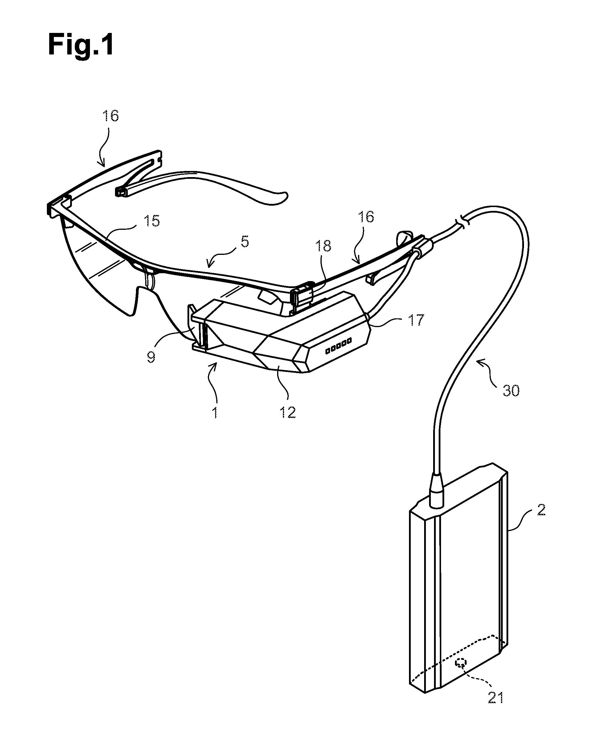
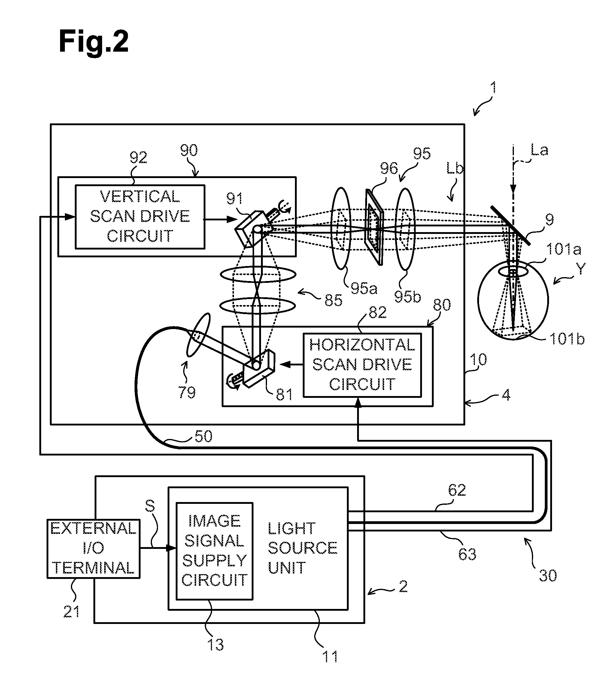
[0036]An optical scanning display according to one embodiment of the present invention will be described below in sequence of the following captions with reference to the drawings. The drawings are referenced to explain technical features that can be employed in this disclosure. The configurations of displays and units, a flowchart of various processes, etc., which are illustrated in the drawings, are merely explanatory examples, and they should not be construed to limit this disclosure. The optical scanning display according to the embodiment is described as a head mounted display of the type mounted to a head of a user and further as a retinal scanning display (hereinafter abbreviated to an “RSD”) that enables the user to visually recognize an image by projecting light to an eye of the user.

[0037]It is noted that various connections are set forth between elements in the following description. It is noted that these connections in general and, unless specified otherwise, may be dir...


PUM


Abstract

A light source unit includes an optical coupler, light sources, a light output portion, a light sensor, and a controller. The optical coupler is formed by joining intermediate portions of plural optical fibers together and multiplexes lights, which have entered respective one ends of the optical fibers, in a coupling region where the intermediate portions of the optical fibers are joined together. The light sources emit light of different wavelengths that enter the respective one ends of the plural optical fibers. The light output portion is formed by the other end of one of the plural optical fibers and outputs the multiplexed lights. The light sensor detects light emerging from the other end of at least another one of the plural optical fibers.

Description

CROSS-REFERENCE TO RELATED APPLICATION[0001]This Application claims priority from JP2010-029304, filed on Feb. 12, 2010, the content of which is hereby incorporated by reference.BACKGROUND OF THE DISCLOSURE[0002]1. Field of the Disclosure[0003]One or more aspects of the disclosure relate to a light source unit that transmits light from a light source through an optical fiber, an optical scanning display, and a retinal scanning display, each display including the light source unit.[0004]2. Description of the Related Art[0005]In a known optical scanning display, an image is formed by two-dimensionally scanning light with varying intensity corresponding to an image signal. As one practical example of the optical scanning display, there is a retinal scanning display for displaying an image by scanning the light and projecting the scanned light to at least one retina of a user.[0006]As illustrated in FIG. 8, the retinal scanning display includes a light source unit 100 and a display unit...

Claims


Application Information

Patent Timeline
Patent Type & Authority Applications(United States)
IPC IPC(8): G03B21/14F21V8/00H05B37/02
CPCA61B3/1225G02B6/00G02B6/2835G02B27/017G02B2027/0112H04N9/3194G02B2027/0178G03B21/14H04N9/3129H04N9/3155H04N9/3161G02B2027/014
Inventor KURIKI, YUICHIROTANAKA, MITSUGI
Owner BROTHER KOGYO KK
Why Eureka
Try Eureka