
Method to determine percentage of damage to structure from single or multiple forces

a technology of structure damage and percentage, applied in the direction of structural/machine measurement, elasticity measurement, instruments, etc., can solve the problems of not addressing the build-up of event intensity, the safferi-simpson scale does not address the ultimate load, and neither of the above methods address the measurement of the applied load (from all sources)

Inactive Publication Date: 2011-08-25
PHELPS MATTHEW B
View PDF0 Cites 24 Cited by
  • Summary
  • Abstract
  • Description
  • Claims
  • Application Information

AI Technical Summary

Benefits of technology

[0028]In accordance with a preferred embodiment of the invention, there is disclosed a process for a physically based mathematically determination of the percentage damage to a structure comprising the steps of: The ultimate load and applied loads are calculated using physical dimensions of the structure, The ultimate load wind speed is calculated from the design wind speed, The applied loads are calculated from actual damaging event data that is relevant to the project site, The ultimate load identifies the poi

Problems solved by technology

The Safferi-Simpson scale does not address the ultimate load (load or combination of loads, which will imitate a structural failure of a specific building or structure).
Most reports only address the peak value of the damaging event and fail to address the build up of the event intensity.
Neither of the above methods address measuring the applied load (from all sources) as it occurs of the entire period of the damaging event.
Neither of the above methods address the point at which the structural failure is initiated or the time by which it is likely complete.
Both of the above methods make the same fundamental flaw that they assume the damage occurred at the events peak intensity.

Method used


Image

  • Method to determine percentage of damage to structure from single or multiple forces
  • Method to determine percentage of damage to structure from single or multiple forces
  • Method to determine percentage of damage to structure from single or multiple forces

Examples


Embodiment Construction

[0037]As required, detailed descriptions of the preferred embodiment are provided herein. It is to be understood, however, that the present invention may be embodied in various forms. The figures are not necessarily to scale; some features may be exaggerated to show details of particular components. Therefore, specific structural and functional details disclosed herein are not to be interpreted as limiting, but rather as a basis for the claims and as a representative basis for teaching one skilled in the art to employ the present invention in virtually any appropriately detailed system, structure or manner.

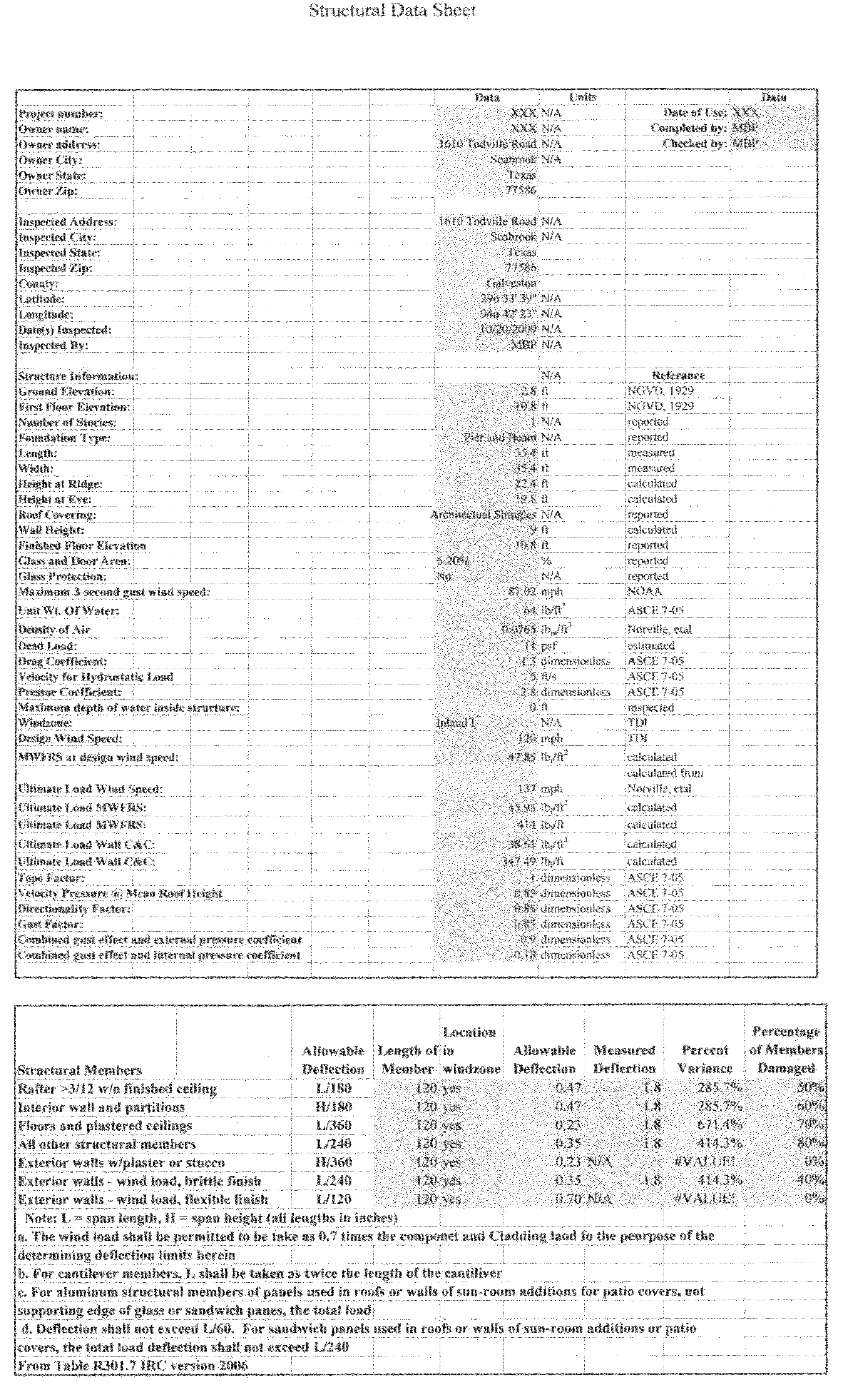
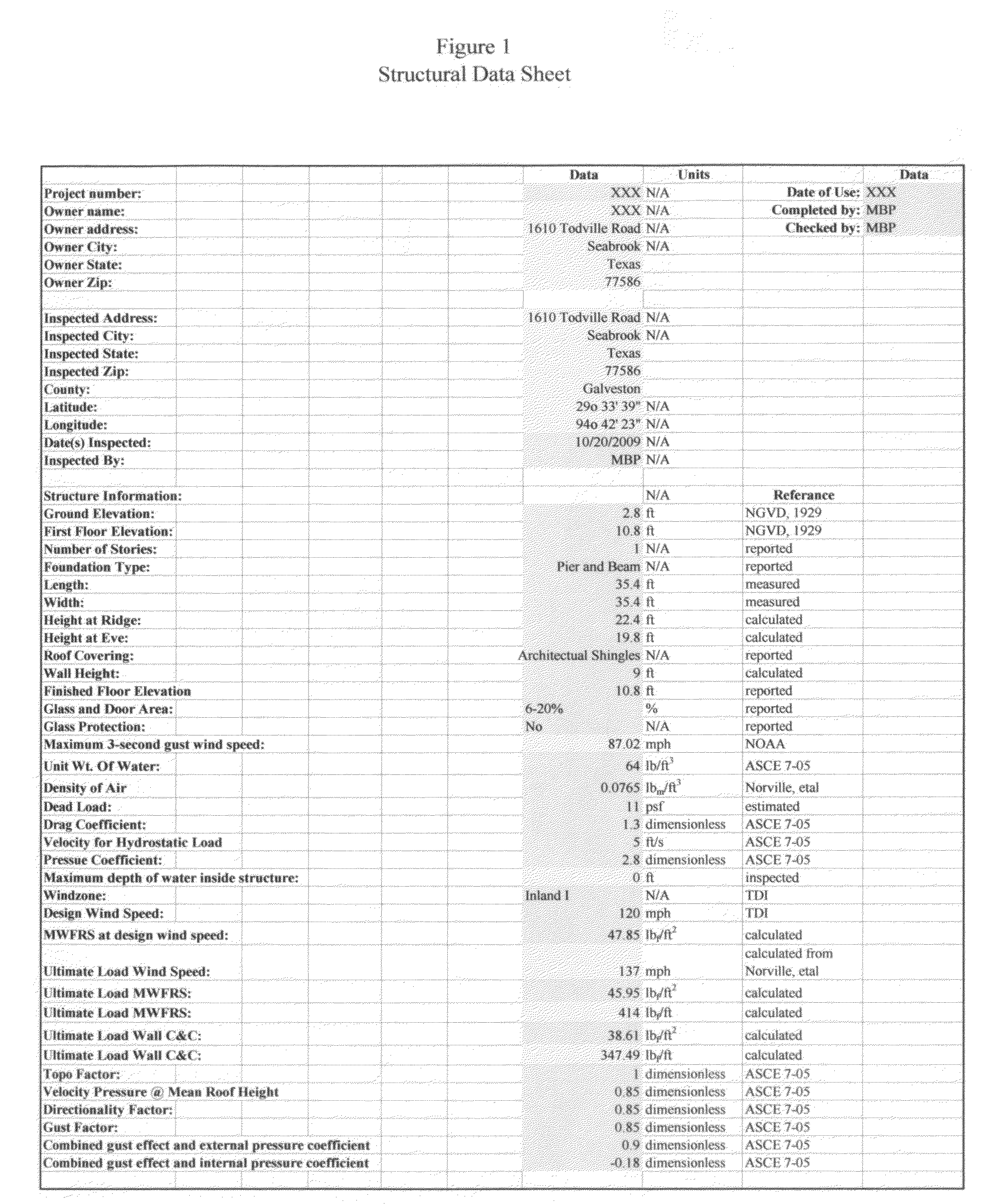
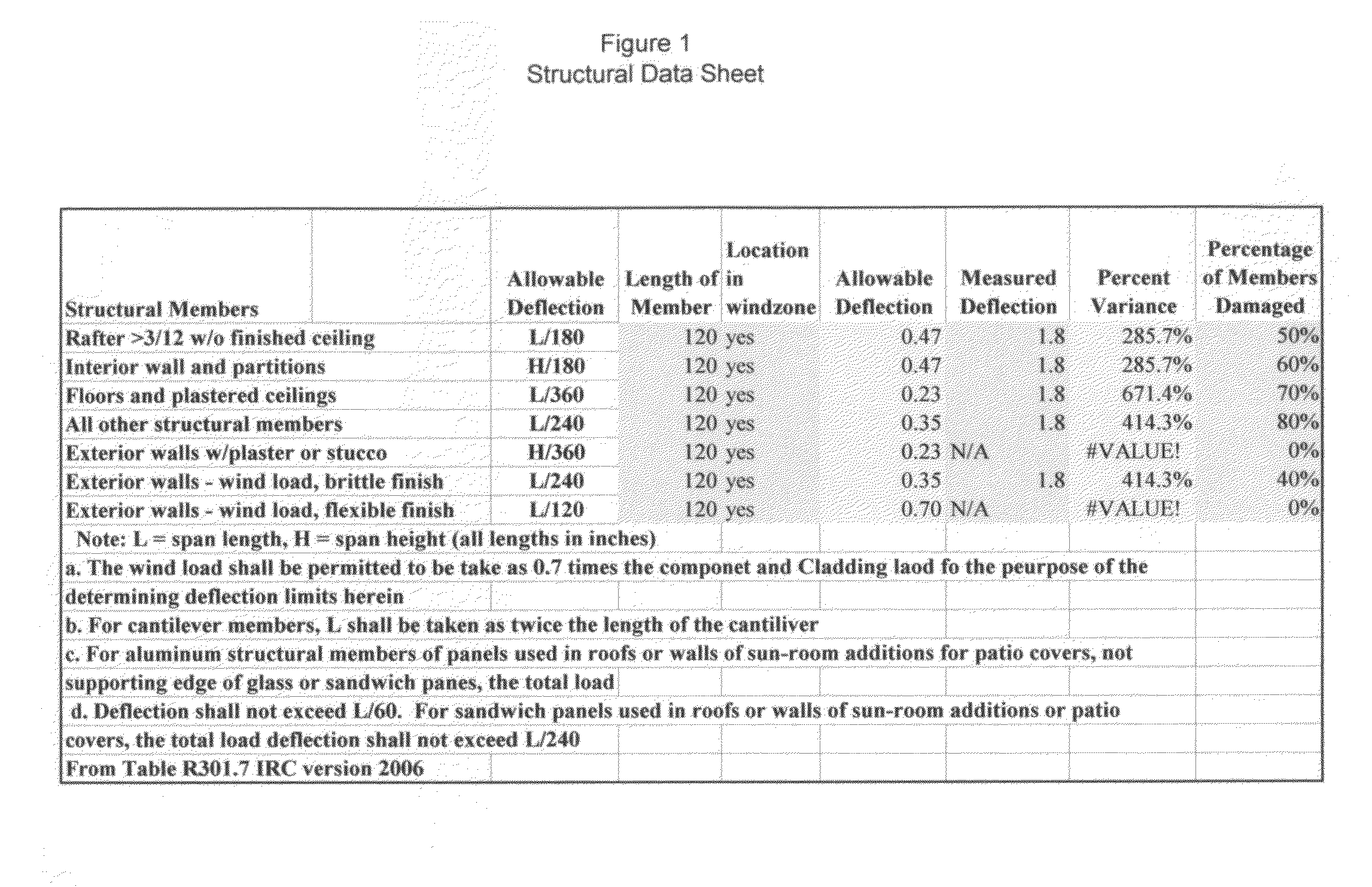
[0038]This patent application is for a physically based mathematically process to determine the percentage of damage, from one or multiply sources, (such as wind and flood) (but not limited to only wind and flood) that cause damage to structures.

This process comprising the following steps of:[0039]1. Determining the location and physical dimensions of the structure;[0040]2. Acquir...


PUM


Abstract

The present invention is directed at providing a numerical analysis method to determine the damage sustained on a structure based upon the physical dimensions of a the structure, the structure's design wind speed and the forces applied during an event such as a hurricane or man made event. The method includes the steps of creating a timeline by which event forces can be plotted and compared to an ultimate load of the structure, individual loads placed upon the structure as well as a sum of the individual loads placed upon the structure. By using this method, the user is able to identify the time at which the ultimate load of the structure was exceeded and the maximum individual and total loads occurred. The method further identifies the time when the structural failure likely initiated and the time by which the structural failure was likely complete. The method further provides a determination of the percentage individual load at the time the ultimate load is breeched as well as a time step of forces applied to the structure throughout the course of the event.

Description

CROSS REFERENCE TO RELATED APPLICATIONS[0001]The Inventor is claiming the benefit of a provisional patent application. Application No. 61 / 303,654, filed Feb. 11, 2010. This provisional patent is the basis for the filing of this Utility Patent. No previous patents pertaining to this subject.STATEMENT REGARDING FEDERALLY SPONSORED RESEARCH OR DEVELOPMENT[0002]This patent has no relationship to any federally sponsored research or development.DESCRIPTION OF ATTACHED APPENDIX[0003]Not ApplicableBACKGROUND OF THE INVENTION[0004]1. Technical Field[0005]This Invention relates generally to the field of forensic engineering investigation, testing and reporting and more specifically to a method to determine the percentage(s) of damage to a structure from a single or multiple forces. More specifically this invention is directed to a process for a physically based mathematically determination of the percentage damage to a structure resulting from single or multiple forces from neutral or man-mad...

Claims


Application Information

Patent Timeline
IPC IPC(8): G01M5/00
CPCG01M5/0033
Inventor PHELPS, MATTHEW B.
Owner PHELPS MATTHEW B
Learn More