
Soft pressure sensing device

a sensing device and soft pressure technology, applied in the field of pressure sensors, can solve the problems of limited service life, unsuitable personal use, and non-adjustable pressure ranges

Active Publication Date: 2011-08-25
THE HONG KONG RES INST OF TEXTILES & APPAREL
View PDF34 Cites 59 Cited by
  • Summary
  • Abstract
  • Description
  • Claims
  • Application Information

AI Technical Summary

Benefits of technology

The present invention provides a pressure sensing device with a first conversion layer and a second conversion layer, an electrically conductive element between them, and a pair of electrically conductive yarns used as connection wires in contact with the electrically conductive element. The first and second conversion layers have at least one deformation member that can deform the electrically conductive element and change its resistivity when pressure is applied on the first or second conversion layer. This invention allows for accurate and reliable pressure sensing in various applications.

Problems solved by technology

However, due to their large size, high rigidity and inflexibility, most of these conventional pressure sensing devices are not wearable by a user, and thus, not suitable to be used for personal usage.
The above-mentioned sensors have numerous shortcomings such as non-adjustable pressure ranges, limited service lifetime, limited sensitivity, and complexity.

Method used


Image

  • Soft pressure sensing device
  • Soft pressure sensing device
  • Soft pressure sensing device

Examples


Embodiment Construction

[0022]Embodiments of the present invention are described below in detail with reference to the accompanied drawings.

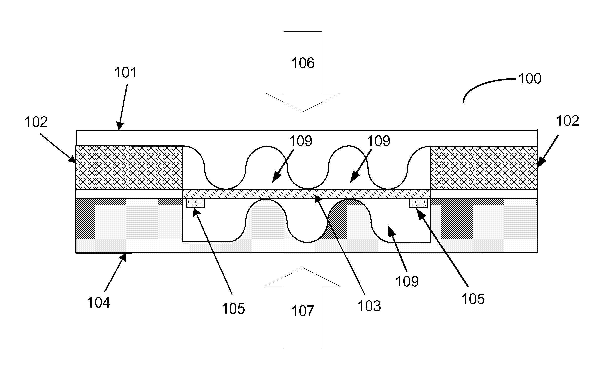
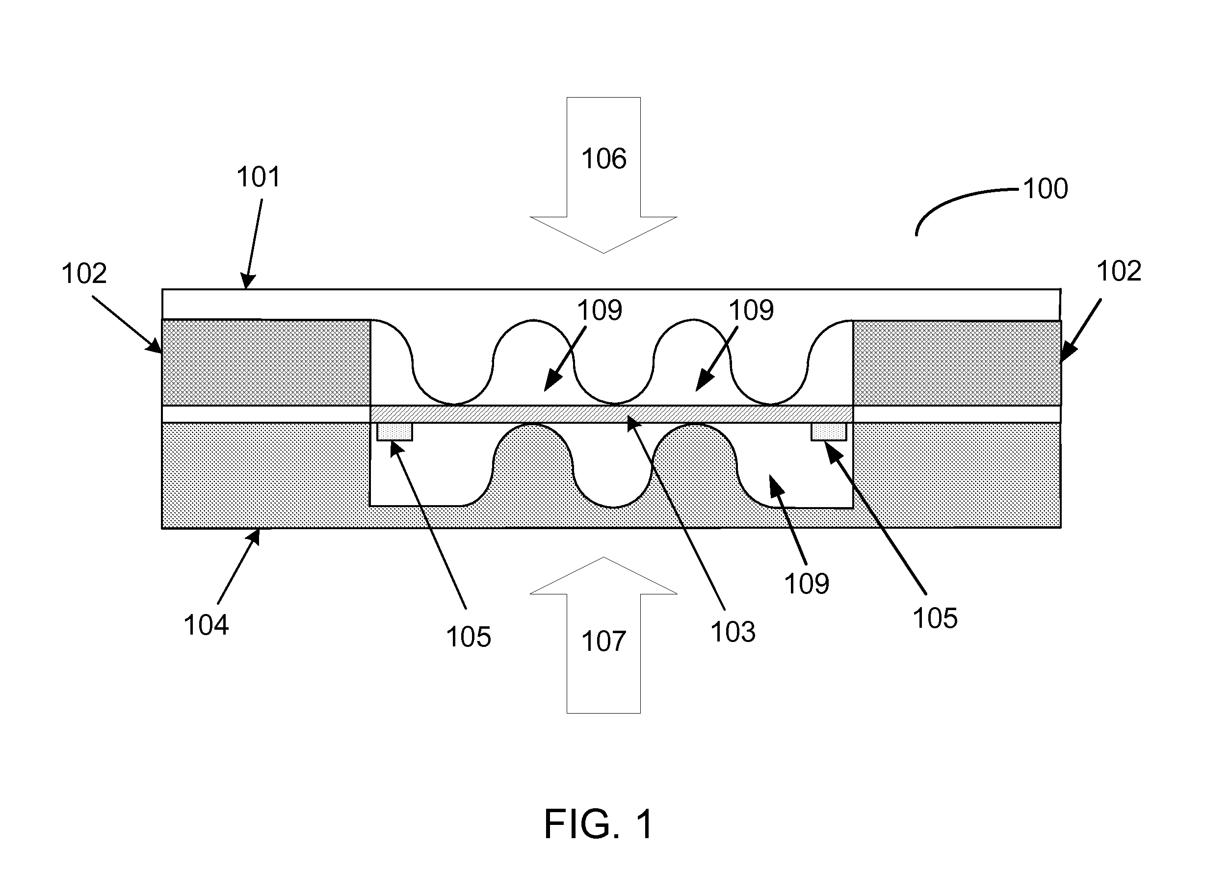
[0023]The present invention provides a compact pressure sensing device with excellent sensitivity. FIG. 1 illustrates an exemplary configuration of a pressure sensing device 100 includes a top conversion layer 101, a bottom conversion layer 104, and a conductive element 103 having contact with a pair of conductive yarns 105, and a pair of modulating blocks 102. The conductive element 103 is sandwiched between the top conversion layer 101 and the bottom version layer 104 with the two ends fixed to the top and bottom layers. The three components may be fixed by various methods such as adhesion or thermal bonding. In another embodiment, modulating blocks 102 with various rigidities can be inserted between the bottom conversion layer 104 and the conductive element 103, or between the top conversion layer 101 and the conductive element 103.

[0024]The top and bottom conversio...


PUM

PropertyMeasurementUnit
pressureaaaaaaaaaa
pressureaaaaaaaaaa
Young's Modulusaaaaaaaaaa

Abstract

A pressure sensing device includes a first conversion layer and a second conversion layer, an electrically conductive element between the first and second conversion layers, and a pair of electrically conductive yarns connected to the electrically conductive element, wherein the first and second conversion layers include at least one deformation member adapted to deform the electrically conductive element and change the resistivity of the electrically conductive element, when pressure exerts on the first and / or the second conversion layer.

Description

BACKGROUND OF THE INVENTION[0001]1. Field of the Invention[0002]The present invention relates to pressure sensors. More particularly, the present invention relates to soft pressure sensors that are sensitive to mechanical stress.[0003]2. Description of the Related Art[0004]Pressure sensors have a wide range of applications from industrial to personal usage. A variety of pressure sensing technologies such as potentiometric, inductive, capacitive, piezoelectric, piezoresistive, optical, flow, and strain gauge pressure sensing have been developed for various applications. However, due to their large size, high rigidity and inflexibility, most of these conventional pressure sensing devices are not wearable by a user, and thus, not suitable to be used for personal usage. Soft and flexible pressure sensors can be used on the surface of three-dimensional shape for mapping or measuring pressures, for example, in athletic sportswears, undergarments, or patients' casts.[0005]Several types of ...

Claims


Application Information

Patent Timeline
Patent Type & Authority Applications(United States)
IPC IPC(8): G01L1/20
CPCA43B3/0005A61B2562/0247G06F3/045G01L1/205G06F3/0414G01L1/20A43B3/44
Inventor TAO, XIAOMINGWANG, YANGYONGHUA, TAOZHU, BOLI, QIAO
Owner THE HONG KONG RES INST OF TEXTILES & APPAREL
Learn More