Method for forming a bevel cut at an end of a wood member

Active Publication Date: 2011-08-25
MEINAN MASCH WORKS INC
View PDF2 Cites 7 Cited by
  • Summary
  • Abstract
  • Description
  • Claims
  • Application Information

AI Technical Summary

Benefits of technology

[0015]The cutout of the of the support table is formed inclined substantially in the same direction of the relative movement between th

Problems solved by technology

In the above method, however, if any part of the end of the wood board 210 has an upward bend or warp 210B as indicated by chain double-dashed line in FIG. 23, such bent part of the end is cut deeper than the other part of the end 210B, with the result

Method used


Image

  • Method for forming a bevel cut at an end of a wood member
  • Method for forming a bevel cut at an end of a wood member
  • Method for forming a bevel cut at an end of a wood member

Examples


first embodiment

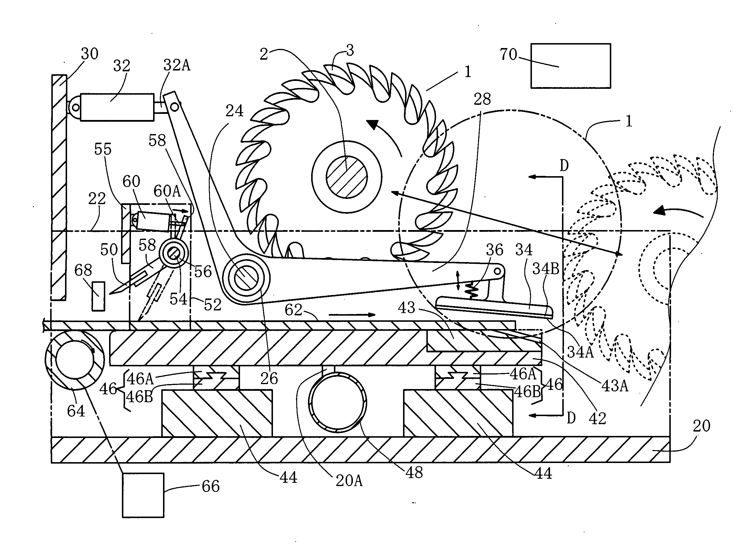
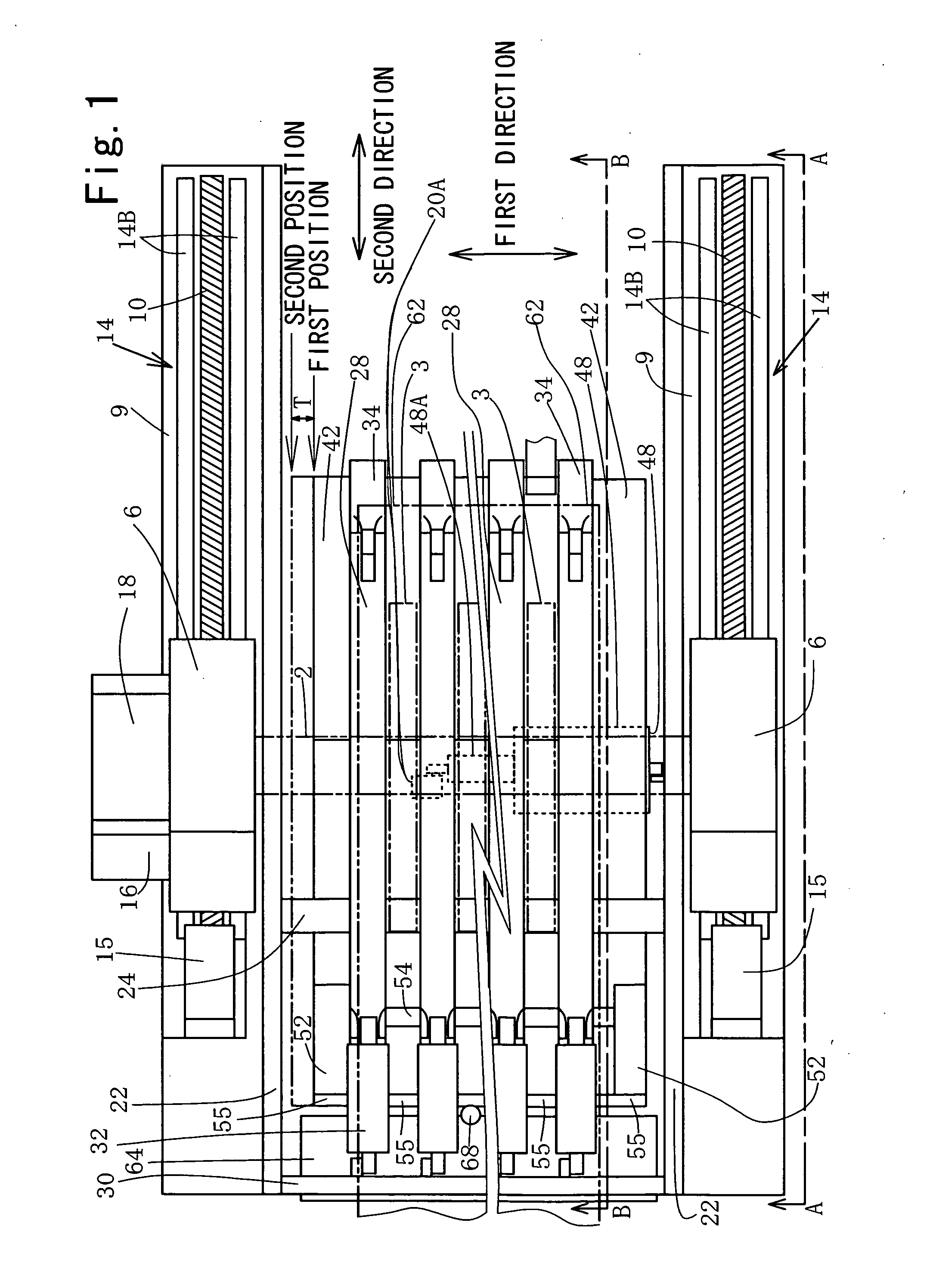
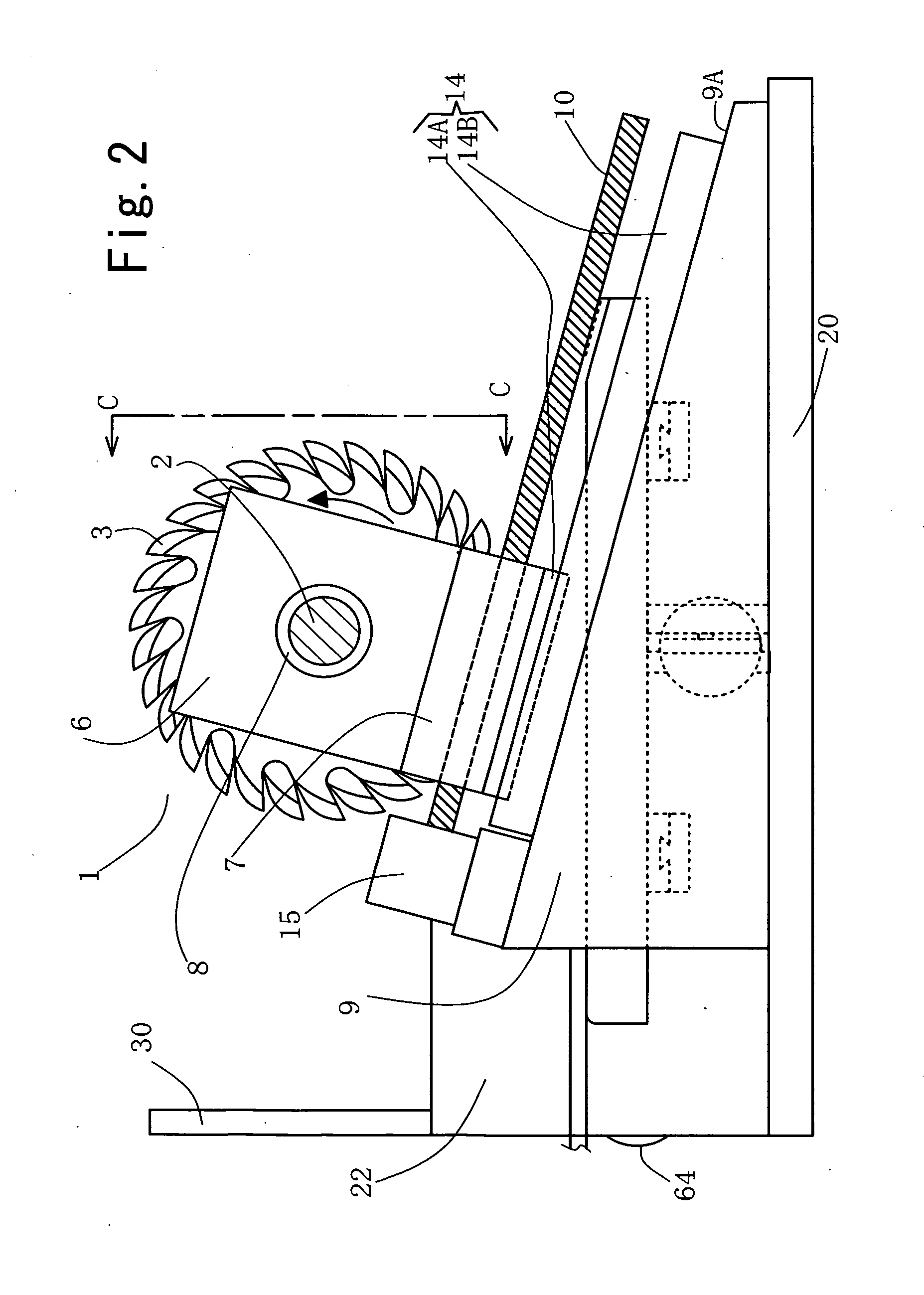
[0039]The following will describe the method for forming a bevel cut at an end of a wood member according to the present invention by way of describing an apparatus used for practicing the method and the operation of the apparatus with reference to FIGS. 1 through 11. In the following description, a plywood board with a rectangular shape having a straight end and with a thickness of about 12 mm will be used as the wood member and such plywood board will be referred to hereinafter as “wood board.”

[0040]Referring firstly to FIGS. 1 through 4, reference numeral 1 designates generally a cutter assembly of the apparatus. As shown in FIG. 4 in detail, the cutter assembly 1 includes a common drive shaft 2, a plurality of cutters 3 mounted on the common drive shaft 2 and each having a cutting width T of about 24 mm, and a plurality of spacers 4 each disposed between any two adjacent cutters 3 and having a width T of about 24 mm corresponding to the width T of the cutter 3. The cutters 3 and...

second embodiment

[0076]The following will describe the bevel cut forming method according to the present invention by way of explaining the operation of the apparatus of FIG. 12.

[0077]In the initial setting of the apparatus, the paired carriage block 88 are placed in their retracted position, as shown in FIG. 12, and the hold-down lever arms 58 are placed in their inoperative position, as indicated by solid line in FIG. 12. The vertical support member 98 is set in its upright position and the slide members 106 are set in their elevated position, respectively, as shown in FIG. 12. The cutter assembly 1 is placed at its raised position as indicated by chain double-dashed line in FIG. 12, the support table 80 is placed in its first position, and the feeding rolls 64 are running in arrow direction.

[0078]With the apparatus thus set in the initial condition, a wood board 62 is placed on the feeding rolls 64 and moved toward the support table 80. As the board sensor 68 detects the arrival of the leading en...


PUM


Abstract

A method for forming a bevel cut at an end of a wood member is disclosed. A wood member is placed on a support table and a plurality of cutters mounted on and spaced along a shaft extending in parallel to the end of the wood member on the table is moved relative to the table in a direction inclined with respect to the wood member thereby to make a first cutting to form a plurality of bevel cuts. The support table is shifted in the direction parallel to the end of the wood member and a second cutting is made by the relative movement between the cutters and the table. During the first and second cutting, the wood member is pressed against the support table by a pressing member at a position adjacent to the end of the wood member and between any two adjacent cutters.

Description

BACKGROUND OF THE INVENTION[0001]The present invention relates to a method for forming a bevel cut at an end of a wood member.[0002]Wood members including wood boards such as plywood, veneer laminated lumber (LVL), fiber board and also sheets such as veneer are joined together in an end-to-end manner in various joints using thermosetting or thermoplastic adhesive for producing a wood member with an increased length. For achieving the desired joint strength, the ends of a wood member are bevel cut so as to enlarge the area of the cut end surfaces to be coated with adhesive. Wood members are assembled with the opposing bevel cut ends coated with adhesive and lapped one on the other and the joining of the wood members is accomplished by allowing the adhesive to be set by heating or cooling depending on the type of the adhesive used.[0003]For increasing the joint strength by further expanding the joint surface area, a wood member is formed at an end thereof with a series of groove-like ...

Claims


Application Information

Patent Timeline
IPC IPC(8): B27M1/08
CPCB27D1/10B27C5/00B27F1/02B27G13/005B27F1/08B27F1/12B27F5/02
Inventor OTSUKA, TOSHIYUKI
Owner MEINAN MASCH WORKS INC
Why Eureka
Try Eureka