Electricity Generation System

a technology of electricity generation system and power generation system, which is applied in the direction of sea energy generation, dc network circuit arrangement, thermoelectric devices, etc., can solve the problems of not being efficient, compact, cost-efficient to manufacture, and/or being optimized for practical use, so as to achieve simplified structure and operation, the effect of improving efficiency

Inactive Publication Date: 2011-08-25
ABB RES LTD
View PDF2 Cites 3 Cited by
  • Summary
  • Abstract
  • Description
  • Claims
  • Application Information

AI Technical Summary

Benefits of technology

[0008]It is an object of the present invention to provide an electricity gene

Problems solved by technology

While the apparatuses described above do convert thermal energy directly to electric energy, they s

Method used


Image

  • Electricity Generation System
  • Electricity Generation System
  • Electricity Generation System

Examples


Embodiment Construction

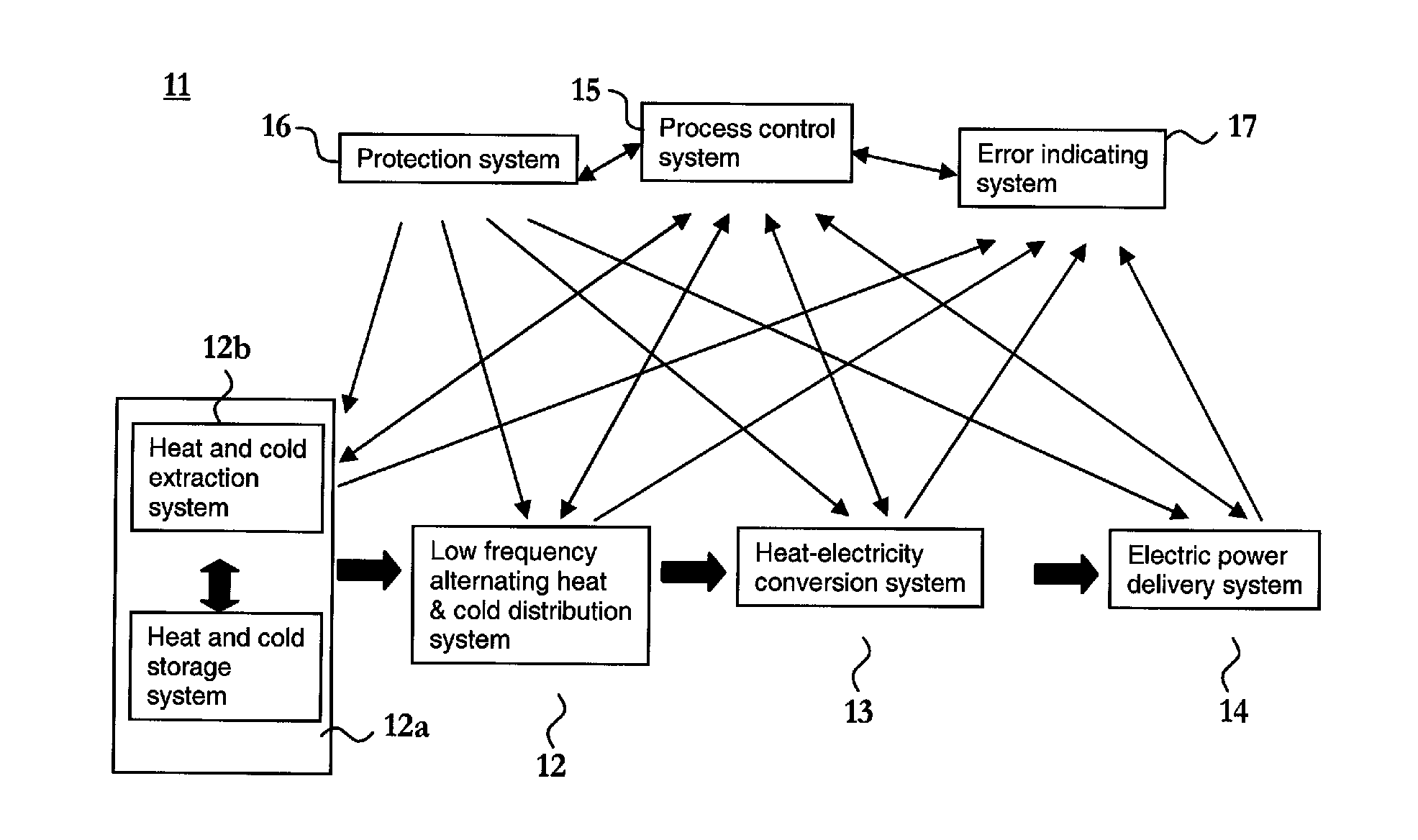
[0022]An electricity generation system 11 according to a general aspect of the present invention, as shown in FIG. 1, comprises a low frequency alternating heat and cold distribution system 12, a heat-electricity conversion system 13, an electric power delivery system 14, and a process control system 15.

[0023]The low frequency alternating heat and cold distribution system 12 is configured to alternately distribute heat and cold to the heat-electricity conversion system 13 at low frequency, preferably at a frequency between about 0.1 and 10 Hz. The heat and cold has advantageously a maximum temperature difference between about 5 and 50 K for each conversion in the heat-electricity conversion system 13.

[0024]The low frequency alternating heat and cold distribution system 12 may be operatively connected to or comprise a heat and cold storage system 12a for storing heat and cold and a heat and cold extracting system 12b for extracting heat and cold from the heat and cold storage system ...


PUM


Abstract

An electricity generation system having a low frequency alternating heat and cold distribution system provided for alternately distributing heat and cold at low frequency; a heat-electricity conversion system operatively connected to the low frequency alternating heat and cold distribution system and provided for generating electricity in response to the alternately distributed heat and cold; an electric power delivery system operatively connected to the heat-electricity conversion system and provided for distributing the generated electricity; and a process control system operatively connected to the low frequency alternating heat and cold distribution system, to the heat-electricity conversion system, and to the electric power delivery system in order to control the operations thereof, is provided.

Description

CROSS-REFERENCE TO RELATED APPLICATIONS[0001]The present application is a continuation of pending International Patent Application PCT / EP2009 / 061883 filed on Sep. 14, 2009 which designates the United States and claims priority from European Patent Application 08165266.1 filed on Sep. 26, 2008, the content of which is incorporated herein by reference.FIELD OF THE INVENTION[0002]The present invention generally relates to an electricity generation system for converting thermal energy to electric energy.BACKGROUND OF THE INVENTION[0003]Apparatuses for transforming thermal energy directly into electric energy using a minimum of moving parts have been known since long.[0004]At the end of the 19'th century, Edison and Tesla described devices based on thermomagnetic materials for converting thermal energy into electricity. Edison's pyro-magnetic generator as described in the British patent No. 16709 includes a thermomagnetic working material, means for magnetizing the working material, sour...

Claims


Application Information

Patent Timeline
IPC IPC(8): H02J3/38H01L35/28
CPCY02E10/34H01L37/04Y02E10/30H10N15/20
Inventor DAHLGREN, MIKAELRUSSBERG, GUNNARTHORBURN, STEFAN
Owner ABB RES LTD
Why Eureka
Try Eureka