Capacitive touch panel with a 'dual layer' force sensor

a capacitive touch panel and force sensor technology, applied in the field of capacitive touch panel devices, can solve the problems of inability to detect the force of touch input, significant limitations, and inability to detect multiple simultaneous touch input events on the surface capacitive type touch panel, and achieve the effect of minimizing the total load capacitance of the first drive electrode section

Active Publication Date: 2014-03-06
SHARP KK
View PDF3 Cites 134 Cited by
  • Summary
  • Abstract
  • Description
  • Claims
  • Application Information

AI Technical Summary

Benefits of technology

[0011]Since the touch sensing electrode does not overlap either of the drive electrode sections, no significant parallel plate capacitances are formed to the touch sensing electrode and the proximity measurement is therefore independent of the force applied by the object. Further, since the force sensing electrode is overlapped completely by the second drive electrode section, no capacitance may be formed between it an object in proximity to the device. The force measurement is therefore independent of the proximity of objects to the device. Further still, since the force sensing electrode overlaps the second drive electrode section and not the first drive electrode section, no...

Problems solved by technology

Although simple in construction and operation, surface capacitive type touch panels are unable to detect multiple simultaneous touch input events as occurs when, for example, two or more fingers are in contact with the touch panel.
However, in spite of the multi-touch capabilities of the projected capacitive method, it has some significant limitations.
For example, it cannot be used to detect the force of touch input and is unable to detect touch input from non-conductive objects such as a plastic stylus or pen.
However, these systems are limited in that they cannot individually measure multiple forces appli...

Method used


Image

  • Capacitive touch panel with a 'dual layer' force sensor
  • Capacitive touch panel with a 'dual layer' force sensor
  • Capacitive touch panel with a 'dual layer' force sensor

Examples


second embodiment

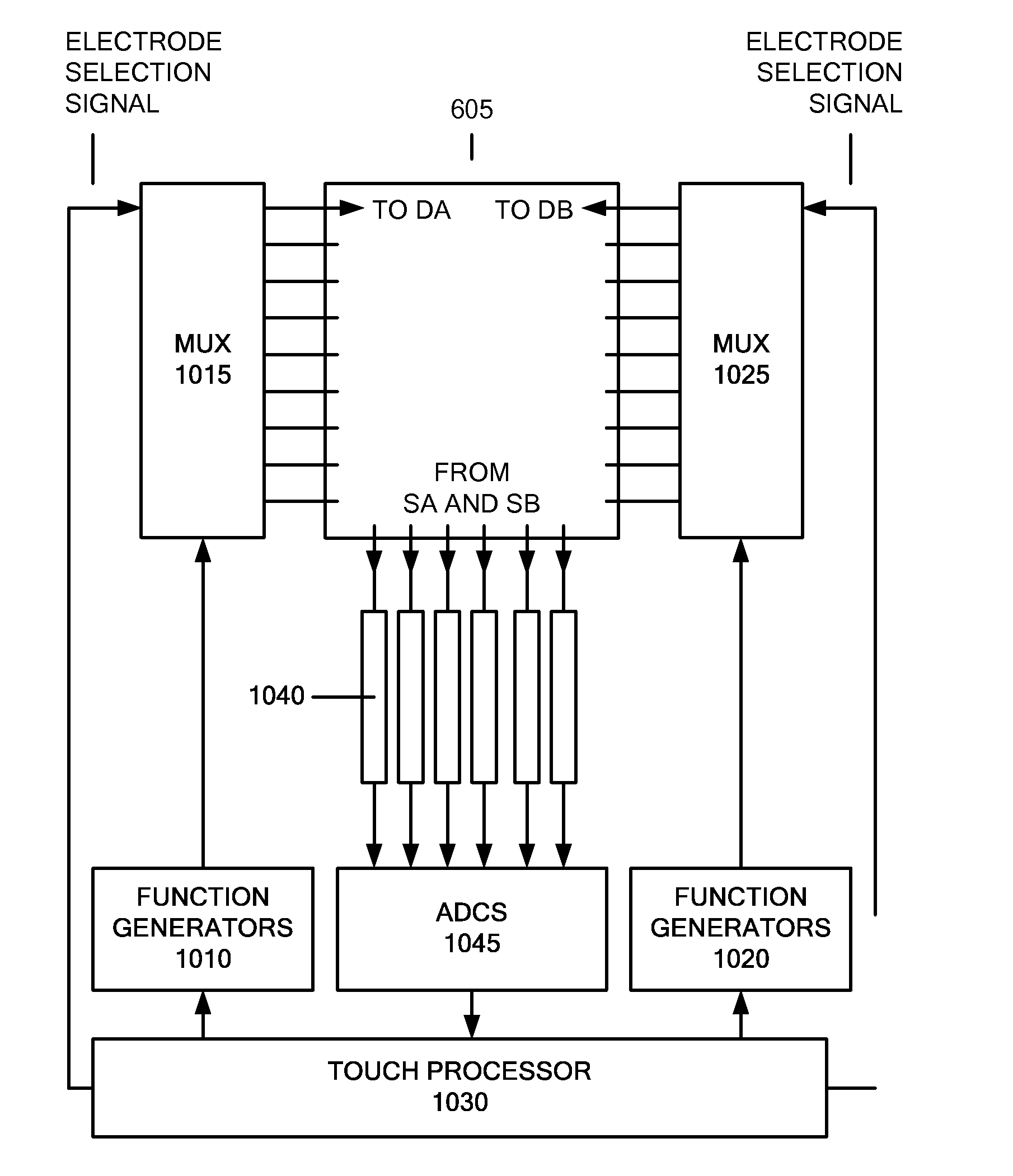
[0113]In a second embodiment, the force sensing electrodes are arranged symmetrically around the touch sensing electrodes (SA) such that throughout the sensor matrix, the geometric centroids of the force measurement locations are coincident with the geometric centroids of the touch measurement locations. This ensures that the force and touch measurement results, obtained from a pair of adjacent force sensing electrodes and touch sensing electrodes, are the product of similar force and touch stimuli. This is advantageous, because it simplifies mathematical determination of the force and touch stimuli from the measurement results. An example of this alternative arrangement of the touch and force sensing electrodes is shown in FIG. 13, where electrical connections 1110 may be made between the two halves of each force sensing portion (SB).

third embodiment

[0114]In accordance with the present invention, the drive and sense electrodes are interdigitated. This involves distributing protrusions of the sense electrodes amongst protrusions of the drive electrodes, in order to maximise the distance over which the electrodes run adjacent and in close proximity to one another. This increases the fringing capacitance between the drive and sense electrodes, and therefore improves the touch sensitivity of the device. An interdigitated electrode geometry for the present invention is shown in FIG. 14. In FIG. 14, the drive electrode is again split into a first drive electrode section DA 1402 (which is used for proximity sensing only) and a second drive electrode section DB 1404 (which plays a role in the force measurement). The sense electrode comprises touch sensing electrodes SA 1406 and force sensing electrodes SB 1408. The force sensing electrodes SB 1408 lie predominantly beneath the second drive electrode sections DB 1404. For clarity, FIG. ...

first embodiment

[0115]As with the first embodiment, it may be desirable to make the force sensing electrodes SB 820 slightly smaller than the second drive electrode sections DB 1404. This reduces unintended coupling through fringing fields between the force sensing electrodes SB 1408 and the first drive electrode sections DA 1402, and therefore avoids unintentional capacitive loading of the first drive electrode sections DA 1402, allowing the touch measurement to be performed at high frequency.

[0116]This third embodiment is operated in the same manner as the first embodiment. The third embodiment may be advantageous over the previous embodiments, because the interdigitated geometry may provide a larger fringing capacitance between the first drive electrode sections DA 1402 and the touch sensing electrodes SA 1406, and may therefore offer a greater signal swing with a higher signal to noise ratio.


PUM


Abstract

A capacitive touch panel includes a first substrate and a second substrate arranged relative to the first substrate. A plurality of drive electrodes are arranged on the first substrate, wherein each drive electrode comprises a first drive electrode section and a second drive electrode section. In addition, a plurality of sense electrodes are arranged on the second substrate, the plurality of sense electrodes including touch sensing electrodes and force sensing electrodes. At least part of a sense electrode of the plurality of sense electrodes forms a force sensitive coupling capacitance with a second drive electrode section and not with a first drive electrode section.

Description

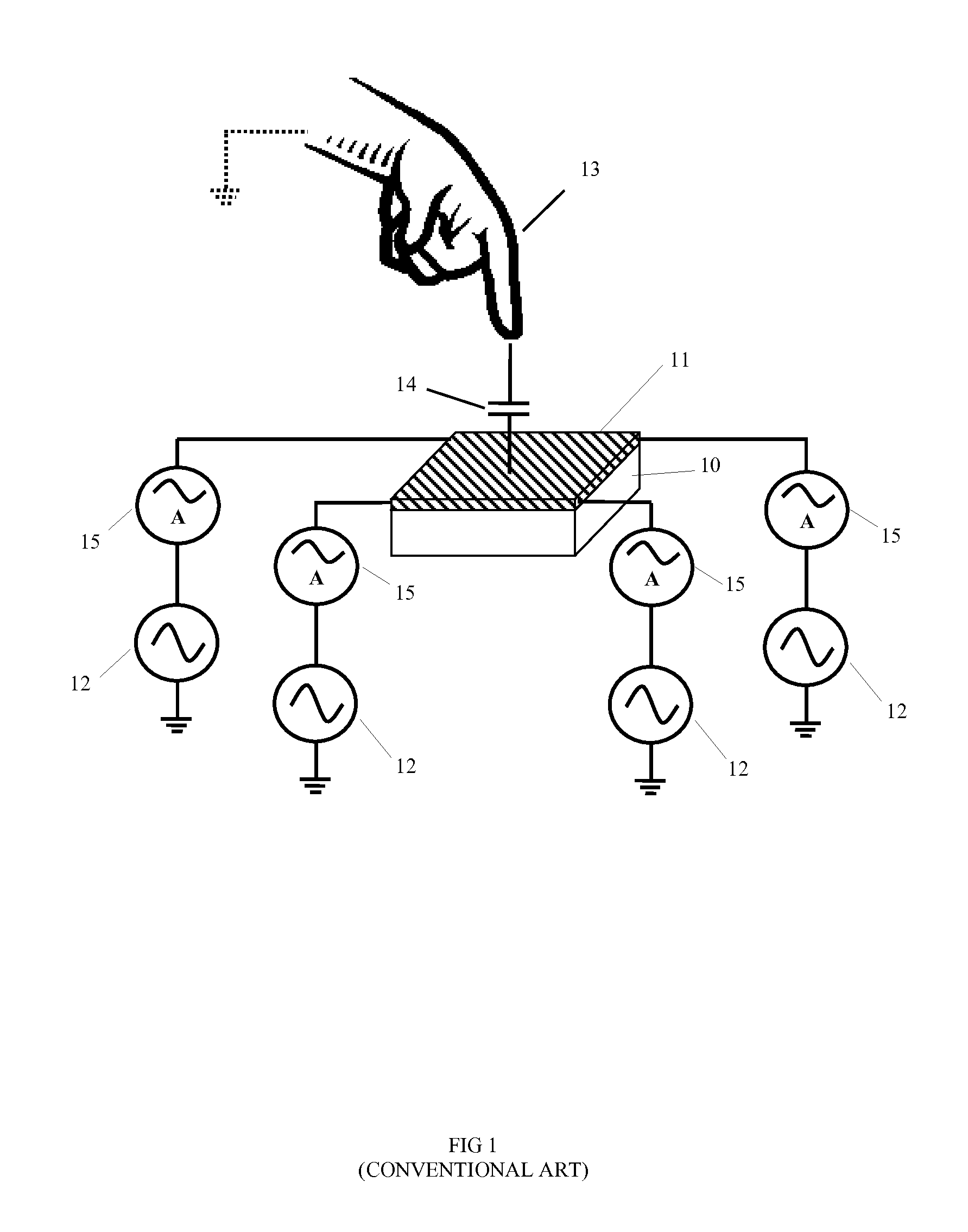
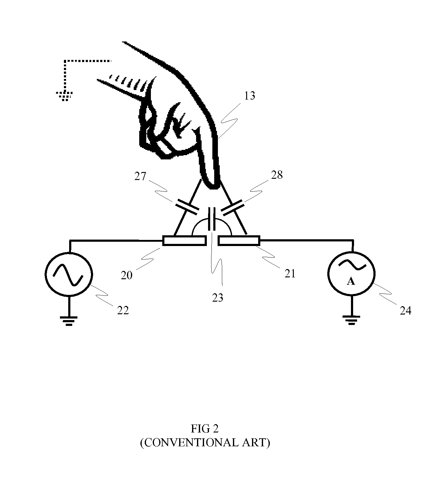
TECHNICAL FIELD AND APPLICATIONS OF THE INVENTION[0001]The present invention relates to touch panel devices and, more particularly, to capacitive type touch panels. A capacitive type touch panel device may find application in a range of consumer electronic products including, for example, mobile phones, tablet and desktop PCs, electronic book readers and digital signage products.BACKGROUND ART[0002]Touch panels have recently become widely adopted as the input device for high-end portable electronic products such as smart-phones and tablet devices. Although, a number of different technologies can be used to create these touch panels, capacitive systems have proven to be the most popular due to their accuracy, durability and ability to detect touch input events with little or no activation force.[0003]The most basic method of capacitive sensing for touch panels is demonstrated in surface capacitive systems, for example as disclosed in U.S. Pat. No. 4,293,734 (Pepper, Oct. 6, 1981). A ...

Claims


Application Information

Patent Timeline
IPC IPC(8): G06F3/044
CPCG06F2203/04106G06F3/0445G06F3/0447
Inventor COULSON, MICHAEL PAULBROWN, CHRISTOPHER JAMESSLAMKUL, DAUREN
Owner SHARP KK
Why Eureka
Try Eureka