Rotating Part Assembly for Motor

Inactive Publication Date: 2011-08-25
SUNONWEALTH ELECTRIC MACHINE IND
View PDF16 Cites 8 Cited by
  • Summary
  • Abstract
  • Description
  • Claims
  • Application Information

AI Technical Summary

Benefits of technology

[0007]It is the primary objective of this invention to provide a rotating part a

Problems solved by technology

However, some motors commonly and currently

Method used


Image

  • Rotating Part Assembly for Motor
  • Rotating Part Assembly for Motor
  • Rotating Part Assembly for Motor

Examples


Embodiment Construction

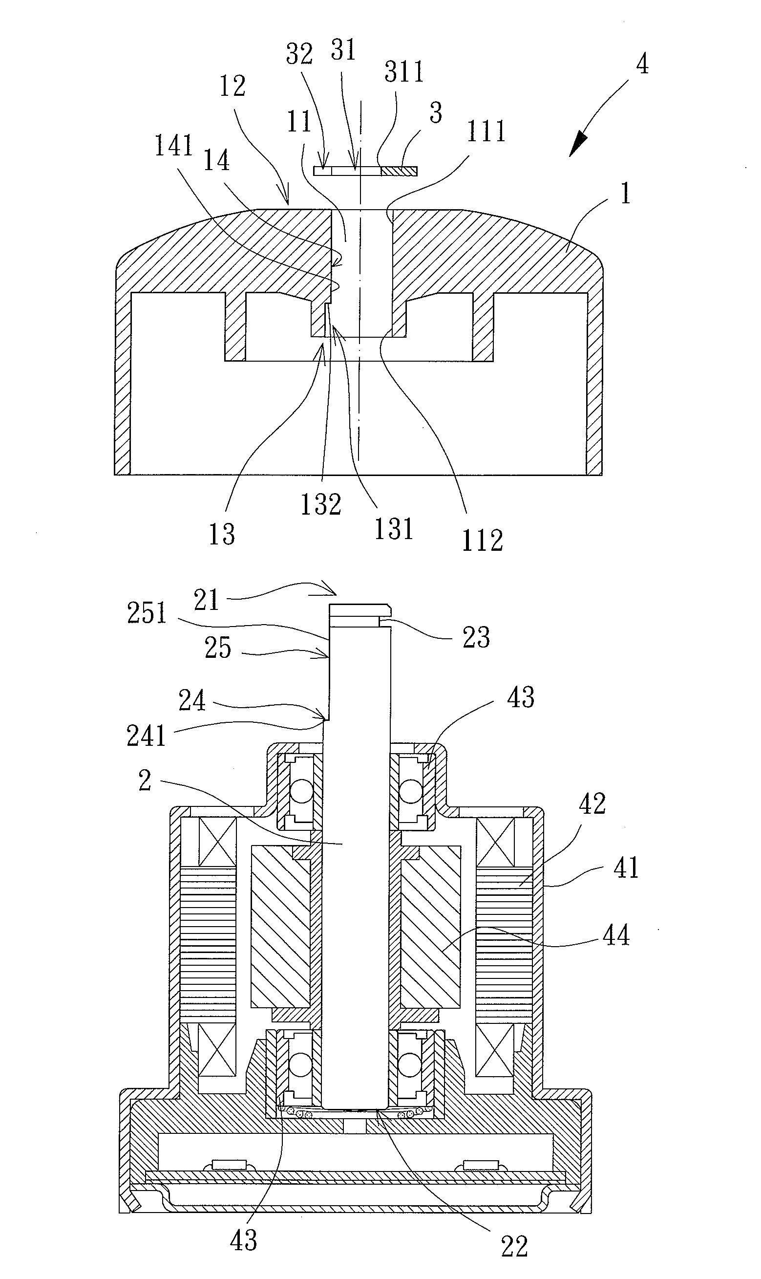
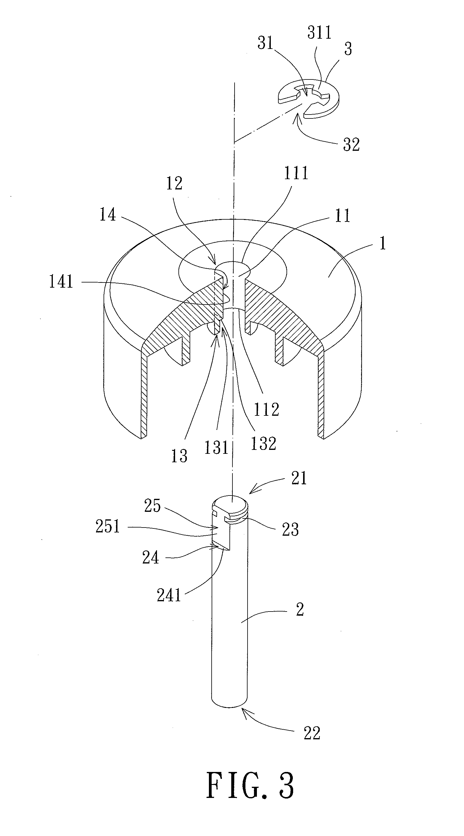
[0028]Referring FIGS. 3 through 5, a rotating part assembly for motor of the present invention includes a hub 1, a shaft 2, and a holding member 3. The hub 1 couples with the shaft 2 and the holding member 3 is mounted on an end of the shaft 2 to prevent the disengagement of the hub 1 from the shaft 2.

[0029]The hub 1 has an assembly channel 11 extending from an outer surface of the hub 1 to an inner surface of the hub 1, so that the assembly channel 11 has a first end 111 disposed at the outer surface of the hub 1 and a second end 112 disposed at the inner surface of the hub 1. Besides, a first abutting portion 12 of the outer surface of the hub 1 encircles and defines the first end 111 of the assembly channel 11. Similarly, a second abutting portion 13 of the inner surface of the hub 1 encircles and defines the second end 112 of the assembly channel 11. Furthermore, a lateral wall delimiting the assembly channel 11 has a first positioning portion 14 between the first end 111 and th...


PUM


Abstract

A rotating part assembly for motor is presented, which includes a hub, a shaft, and a holding member. The hub has an assembly channel with a first end and a second end, with a first abutting portion encircling and defining the first end and a second abutting portion encircling and defining the second end, with a first positioning portion arranged between the first end and the second end of the assembly channel. The shaft extends through the assembly channel of the hub and provides a first end section and a second end section, wherein an engaging slit aligning with the first abutting portion, an engaging shoulder aligning with the second abutting portion, and a second positioning portion facing the first positioning portion are disposed at the first end section. The holding member inserts into and couples with the engaging slit and abuts the first abutting portion of the hub.

Description

BACKGROUND OF THE INVENTION[0001]1. Field of the Invention[0002]The present invention relates to a rotating part assembly, particularly to a rotating part assembly for motor.[0003]2. Description of the Related Art[0004]Referring to FIG. 1, a conventional motor structure is shown. The motor structure comprises a motor 8 including a base 81, a stator 82 and a rotor 83. The base 81 couples with a shaft tube 811, with the stator 82 mounted on the shaft tube 811. The rotor 83 includes a hub 831, a shaft 832, and a permanent magnet 833. The hub 831 couples with an end of the shaft 832 by injection molding, while the other end of the shaft 832 rotatably couples with and extends into the shaft tube 811. The permanent magnet 833 is mounted on an inner surface of the hub 831. With the above-described structure, the rotor 83 is actuated to rotate while the stator 82 is electrified to generate an alternative magnetic field. Specifically, a motor of similar structure like the motor 8 is usually ...

Claims


Application Information

Patent Timeline
IPC IPC(8): F16C35/08
CPCF04D25/064F04D29/329F04D29/263
Inventor HORNG, ALEXCHUANG, HUNG-JEN
Owner SUNONWEALTH ELECTRIC MACHINE IND
Why Eureka
Try Eureka