
Open End Wrench Capable of Fast Driving

Active Publication Date: 2011-12-22
HU BOBBY
View PDF2 Cites 11 Cited by
  • Summary
  • Abstract
  • Description
  • Claims
  • Application Information

AI Technical Summary

Benefits of technology

[0016]Preferably, the sliding face of the slide has a first curvature. The sliding wall of the sliding groove has a second curvature equal to the first curvature. The sliding face of the slide is smoothly slideable along the sliding wall of the sliding groove. The sliding face is adapted to transmit reactive force from the workpiece to the sliding wall and to avoid concentration of stress on the slide, increasing torque bearing capacity of the slide when the workpiece is driven by the body to rotate.
[0017]Preferably, the guiding slot has a third curvature equal to the second curvature, allowing relative smooth, arcuate sliding between the guiding groove of the slide and the guide in the sliding groove without operational interference therebetween.
[0024]The inner faces of the first and second wings are adapted to contact with the outer periphery of the workpiece received in the wrenching space to increase a contact area between the workpiece and the slide. The outer faces of the first and second wings are spaced from the body to avoid friction between the body and the first and second wings, allowing smooth sliding movement of the slide between the extended position and the retracted position.

Problems solved by technology

However, the structural strength of the wrench is insufficient for high-torque operation, as the movable jaw merely encloses the guide and is not enclosed by other members.
Furthermore, the guide is irregularly formed in a wrenching space of the wrench, leading to difficulties in processing.
Further, the exposed portion of the spring, when compressed by the movable jaw, is liable to bend and, thus, in frictional contact with the end edges of the bores of the stationary and movable jaws, leading to non-smooth compression of the spring or even permanent deformation of the spring.
Further, the exposed portion of the spring is apt to be contaminated by oil to which debris easily adheres.
Such a structure is difficult to process.
Furthermore, assembly of the open end ratchet wrench is troublesome.
Further, the pawl is merely enclosed at both sides and has insufficient structural strength in the lateral direction.
When the nut is tightened to a position adjacent to an object to be fixed, wear or damage to the nut may occur if the nut has insufficient contact area or has a small volume.
Such a wrench is particularly suitable for rotating pipes, but not suitable for tightening or loosening fasteners such as bolts, nuts, or the like.
However, the stationary jaw is enclosed by the movable plate such that the contact area between the stationary jaw and the workpiece is significantly decreased.
However, it is difficult to form the auxiliary jaw retracting opening in the second jaw, which is particularly true for axial drilling.
However, if the nut is of a smaller thickness or if the nut is moved to a position adjacent to a surface of an object to be tightened such that the width of the side of the nut is smaller than the extent of the pushing face and the driving surface, the pushing face and the driving surface may be worn or damaged due to insufficient contact area with the side of the nut.
The driving operation provided by the wrench is not smooth.

Method used


Image

  • Open End Wrench Capable of Fast Driving
  • Open End Wrench Capable of Fast Driving
  • Open End Wrench Capable of Fast Driving

Examples


Embodiment Construction

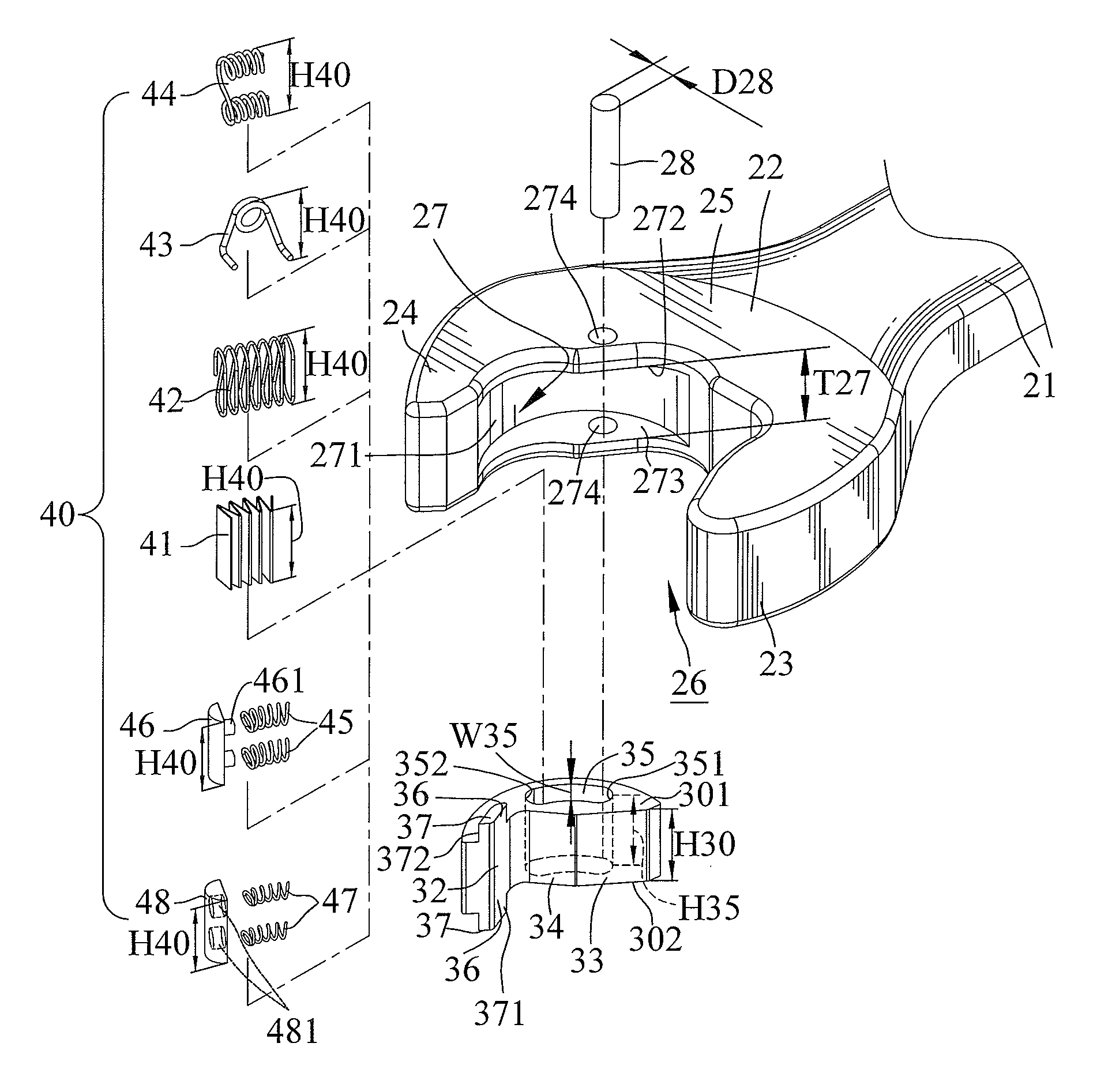
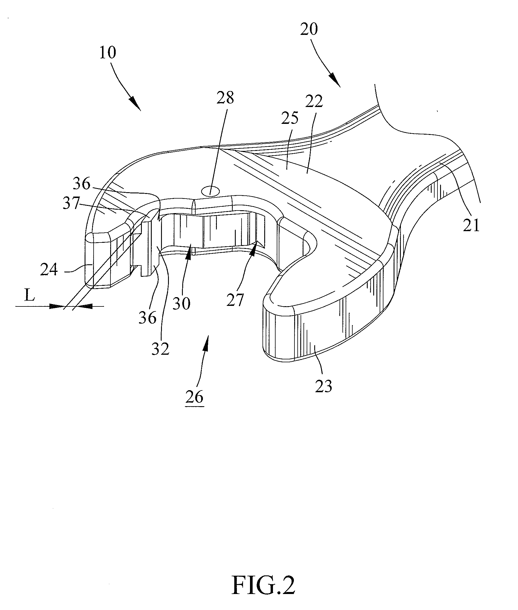
[0052]FIGS. 2-12 show an open end wrench 10 according to the present invention. In the form shown, open end wrench 10 includes a body 20, a slide 30, and an elastic device 40. Body 20 includes a handle 21 and a jaw portion 22 formed on an end of handle 21. Jaw portion 22 can hold a workpiece 90, such as a hexagonal head of a bolt, a nut, or the like. Workpiece 90 includes an outer periphery having first, second, third, fourth, fifth, and sixth sides 91, 92, 93, 94, 95, and 96 respectively having first, second, third, fourth, fifth, and sixth force-receiving faces in a first rotating direction 91A, 92A, 93A, 94A, 95A, and 96A. First, second, third, fourth, fifth, and sixth sides 91, 92, 93, 94, 95, and 96 of workpiece 90 respectively have first, second, third, fourth, fifth, and sixth force-receiving faces in a second rotating direction 91B, 92B, 93B, 94B, 95B, and 96B. A user can grip the handle 21 and rotate body 20 as well as jaw portion 22 about axis C of workpiece 90 to tighten ...


PUM


Abstract

An open end wrench includes first and second jaws. The first jaw includes an arcuate sliding groove having two support walls and an arcuate sliding wall between the support walls. A slide is slideably received in the sliding groove and includes an arcuate sliding face slideable along the sliding wall. Two wings respectively extend from top and bottom faces of the slide. Top and bottom extension faces extend from a wrenching face of the slide and are located on inner faces of the wings. A spacing is formed between an outer face of each wing and one of the support walls to avoid friction, allowing smooth movement of the slide between an extended position and a retracted position.

Description

CROSS REFERENCE TO RELATED APPLICATION[0001]This is a continuation-in-part application of U.S. patent application Ser. No. 12 / 890,767 filed Sep. 27, 2010.BACKGROUND OF THE INVENTION[0002]The present invention relates to an open end wrench capable of fast driving and, more particularly, to an open end wrench capable of fast driving a workpiece without the risk of undesired shifting from the workpiece.[0003]U.S. Pat. No. 1,320,668 discloses a wrench including a stationary jaw and a movable jaw slideable along a guide. The movable jaw is forced against an abutment at an outer end of the guide by a spring bearing against the stationary jaw. An end of the spring is received in a bore in the stationary jaw. The other end of the spring is received in another bore in the movable jaw. An intermediate portion of the spring is exposed between the stationary jaw and the movable jaw. When the user is intended to tighten or loosen a nut, the wrench is turned in a driving direction during which op...

Claims


Application Information

Patent Timeline
IPC IPC(8): B25B13/12
CPCB25B13/46
Inventor HU, BOBBY
Owner HU BOBBY
Features
  • Generate Ideas
  • Intellectual Property
  • Life Sciences
  • Materials
  • Tech Scout
  • Unparalleled Data Quality
  • Higher Quality Content
  • 60% Fewer Hallucinations
Learn More