Luer connector

Inactive Publication Date: 2012-05-17
WESTMED
View PDF14 Cites 31 Cited by
  • Summary
  • Abstract
  • Description
  • Claims
  • Application Information

AI Technical Summary

Benefits of technology

[0010]It is one aspect of embodiments of the present invention to provide a luer connector that is used to join a tube to a medical instrument. In one specific embodiment, a luer lock connector is provided wherein a male luer connector, which is associated with a medical instrument, is interconnected to a female luer connector, which is associ

Problems solved by technology

Because connectors are used for a variety of different purposes and with a variety of fluids such as gases, blood, and other fluids, connecting the wrong equipment to the wrong tube or line is a potential concern.
Misconnections can cause damage to equipment and/or perhaps injury to the patient.

Method used


Image

  • Luer connector
  • Luer connector
  • Luer connector

Examples


Embodiment Construction

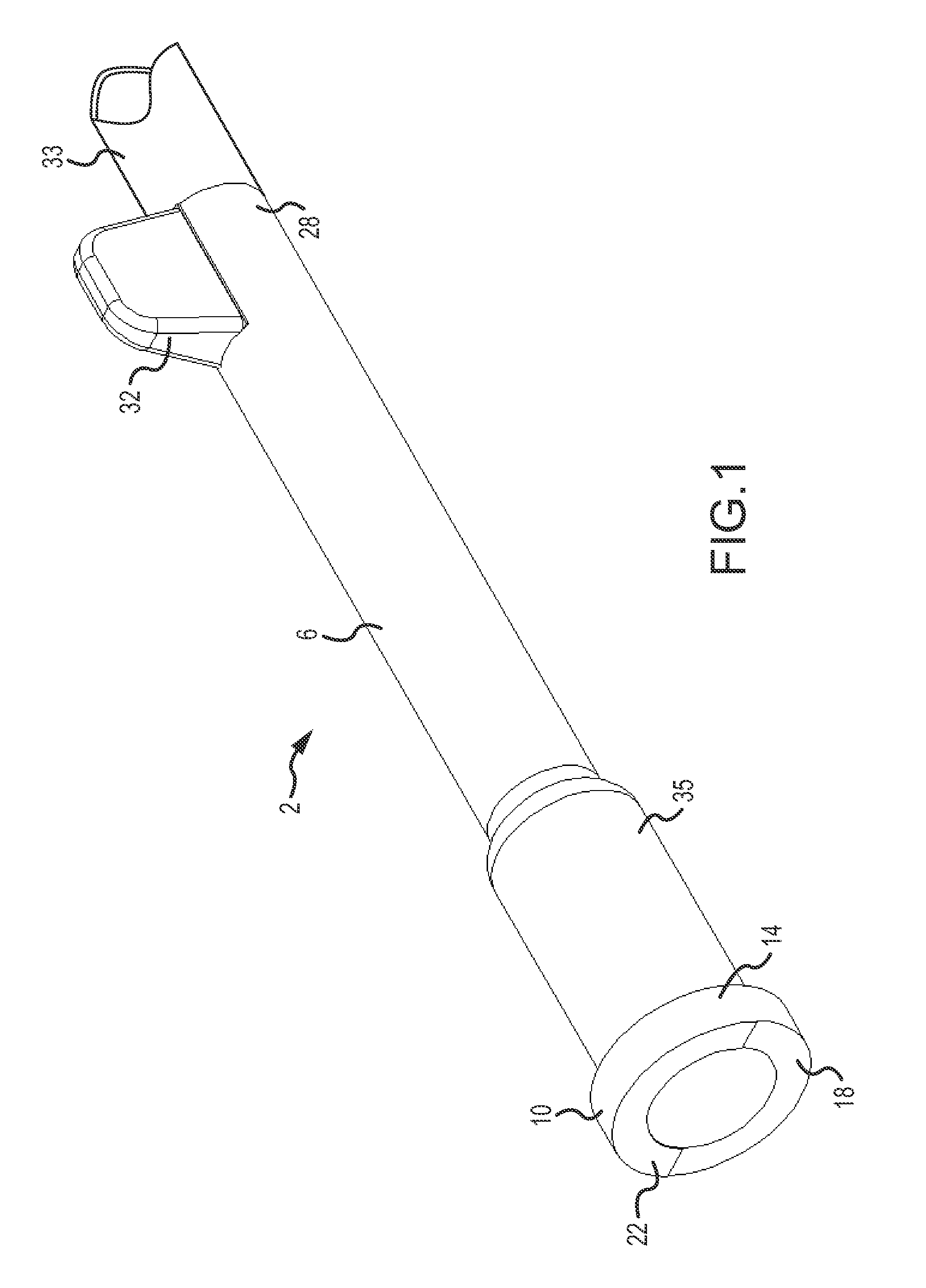
[0027]FIG. 1 shows a female luer connector 2 that comprises a cylindrical hollow body 6 having an annular flange 10 disposed at a first end 14 that is designed to interface with a male luer connector of a medical instrument, such as a capnograph. A portion of a face 18 of the annular flange 10 is coated with a reflective material 22 that at least partially covers approximately one-quarter to one-half of the face 18. It should be understood that the reflective material is intended to orient with sensors associated with a medical instrument and, therefore, may not be continuous, but may be found on the annular flange in any appropriate pattern. A second end 28 of the female luer 2 includes an upstanding flange or fin-like portion 32. The second end 28 interconnects to an oxygen tube 33, for example, that extends to a patient. The hollow body 6 of the female luer 2 may comprise an increased diameter portion 35 with an increased outer diameter.

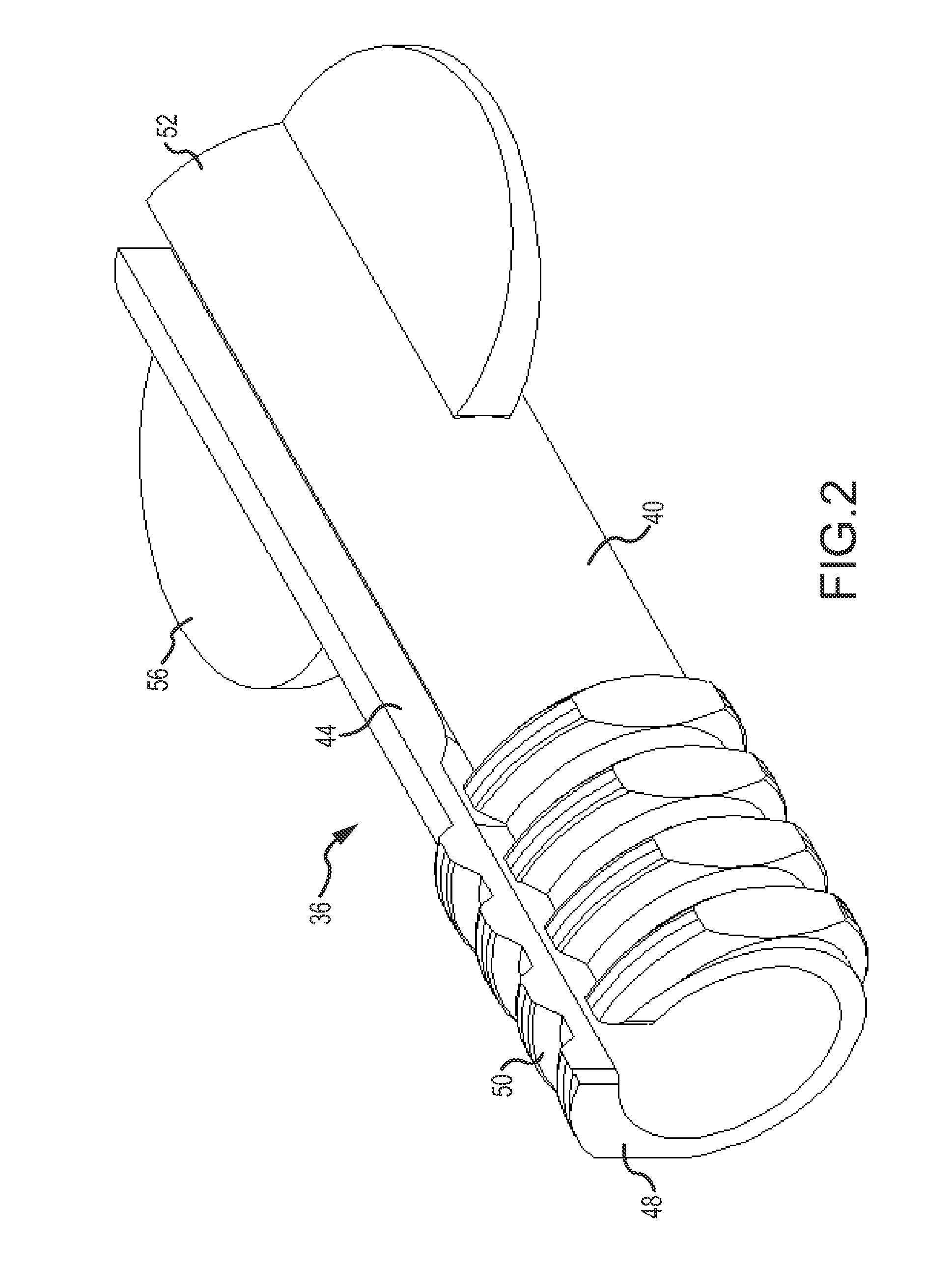
[0028]FIG. 2 shows a floating nut 36 that i...


PUM


Abstract

A luer connector is provided having a first member that includes an end face with a reflective material that does not cover the entire end face wherein the first member is selectively rotatable to align the reflective portion with sensors of the medical instrument. The first member is adapted to freely rotate within a second member that is used to connect the first member to the medical instrument.

Description

[0001]This application claims the benefit of U.S. Provisional Patent Application Ser. No. 61 / 414,323, filed Nov. 16, 2010, the entire disclosure of which is incorporated by reference herein.FIELD OF THE INVENTION[0002]Embodiments of the present invention generally relate to sensing the presence and verifying the identity of a tube connector. More specifically, a tube connector is provided that will be accepted by electro-optical sensors of a medical testing instrument, thereby allowing the instrument to perform its intended function.BACKGROUND OF THE INVENTION[0003]Capnographs are medical instruments for analyzing exhaled air. Capnographs include a breathing tube, also called a sampling line having a first end connected to an air passageway of a respirator or to a cannula. A second end of the tube comprises a connector that mates with a complimentary connector on the medical instrument. In some situations, the connectors are unique such that the instrument will only function if the ...

Claims


Application Information

Patent Timeline
IPC IPC(8): A61M25/16
CPCA61B5/097A61M39/10A61B2562/226A61M2039/1094A61M2039/1044A61M2039/1077A61M2025/0008
Inventor MCKINNON, ROBERT J.BICKLEY, JAMES DALE
Owner WESTMED
Why Eureka
Try Eureka