Polymeric Prosthetic Liner With Controlled Stretch Characteristics

a polymer prosthetic and stretchable technology, applied in the field of fabric-covered polymeric prosthetic lines, can solve the problems of inability to completely prevent or completely inhibit the stretching of the liner in the longitudinal direction, the associated liner and the length of the residual limb is also highly stretchable. achieve the effect of facilitating the connection of the liner and increasing comfor

Active Publication Date: 2011-08-25
WILLOWWOOD GLOBAL LLC
View PDF99 Cites 32 Cited by
  • Summary
  • Abstract
  • Description
  • Claims
  • Application Information

AI Technical Summary

Benefits of technology

[0013]A liner of the present invention is comprised of a polymeric material with a specially designed fabric outer covering. The polymeric material may be, without limitation, silicone, urethane, or a thermoplastic elastomer (TPE). Of particular interest are block copolymer and mineral oil gel compositions, as such materials have proven to be especially effective at cushioning and protecting residual limbs while simultaneously providing amputees with a high level of comfort.
[0015]Because the polymeric material of the liner interior will be in contact with the skin of a residual limb when the liner is worn, the polymeric material is generally smooth and continuous in nature such there are no seams or other discontinuities that may cause amputee discomfort. A liner of the present invention will typically protect and cushion the entire portion of a residual limb residing in a prosthetic socket.
[0016]While a liner of the present invention may be of the cushioning liner variety, other embodiments are constructed as locking liners. To this end, a liner of the present invention may include a docking element at the closed end for facilitating connection of the liner to the socket of a prosthetic limb. Such docking elements may be designed with a special accordion shape that provides for increased comfort when the liner is worn by better conforming to the distal shape of the residual limb.
[0018]Manipulating the physical properties of the polymeric material portion of a liner of the present invention may also be used to assist with controlling longitudinal liner stretching. That is, in conjunction with the use of a stretch-controlling fabric as described above, the polymeric material itself may also be rendered less stretchable, such as by reducing the amount of mineral oil and / or other plasticizer(s) present therein and / or by adding a reinforcing material such as KEVLAR thereto.

Problems solved by technology

While polymeric gel materials provide amputees with a great deal of cushioning and comfort, it is well known that such gels are also highly stretchable.
However, and particularly with respect to locking liners or cushion liners used with vacuum suspension systems, the stretchable nature of these gel materials may allow for the associated liner to stretch to an undesirable degree along the length of the residual limb (i.e., in a longitudinal direction).
Consequently, employing a technique that overly inhibits stretching of a liner in a circumferential direction or that completely prevents stretching of a liner in a longitudinal direction is generally unacceptable.
As should be apparent, the use of liners by BK amputees presents yet another problem when attempting to limit the longitudinal stretch of a liner.
Particularly, because the knee joint bends while covered by the liner, and because the polymeric gel of the liner clings to the skin of the residual limb, providing a BK amputee with a liner that exhibits no longitudinal elasticity or that has overly limited longitudinal stretch characteristics, can hinder or render uncomfortable bending of the knee joint.
This may result from the knee joint struggling to stretch the liner and / or from the polymeric gel material pulling against the skin of the anterior portion of the knee joint.
As would be apparent, a similar problem would exist in the case of a liner that covers the elbow joint of an upper extremity amputee.
None of these techniques have provided acceptable results.
The embedment or attachment of reduced stretch materials to a liner has proven ineffective at controlling the overall longitudinal stretch thereof.
Covering an entire liner with a non-stretch material or a material of greatly reduced stretch is undesirable for the reasons articulated above.

Method used


Image

  • Polymeric Prosthetic Liner With Controlled Stretch Characteristics
  • Polymeric Prosthetic Liner With Controlled Stretch Characteristics
  • Polymeric Prosthetic Liner With Controlled Stretch Characteristics

Examples


Embodiment Construction

)

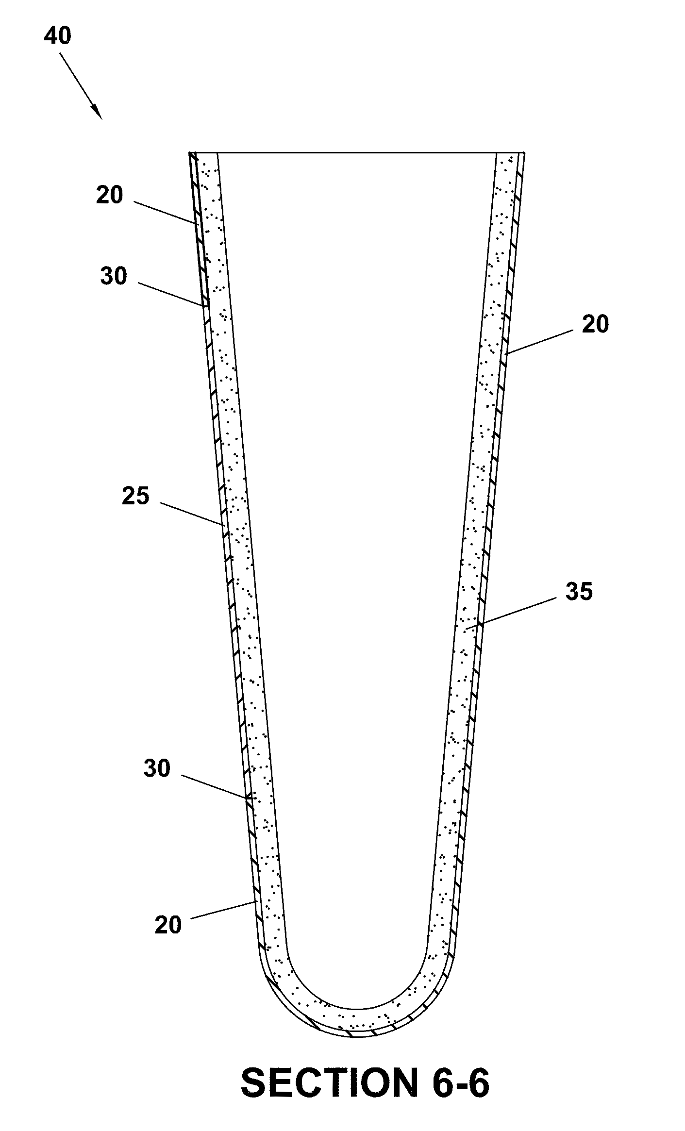
[0031]Exemplary embodiments of a controlled-stretch prosthetic liner of the present invention are described below. These exemplary embodiments are provided solely for the purpose of illustration, and not limitation. As described above, each embodiment includes an inner layer of polymeric material and an outer layer of fabric. With respect to the cross-sectional views illustrated herein, it should be noted that the thickness of the fabric layers and the polymeric material layers has been exaggerated for clarity. Further, the fabric layers and polymeric material layers are not necessarily drawn to scale with respect to each other.

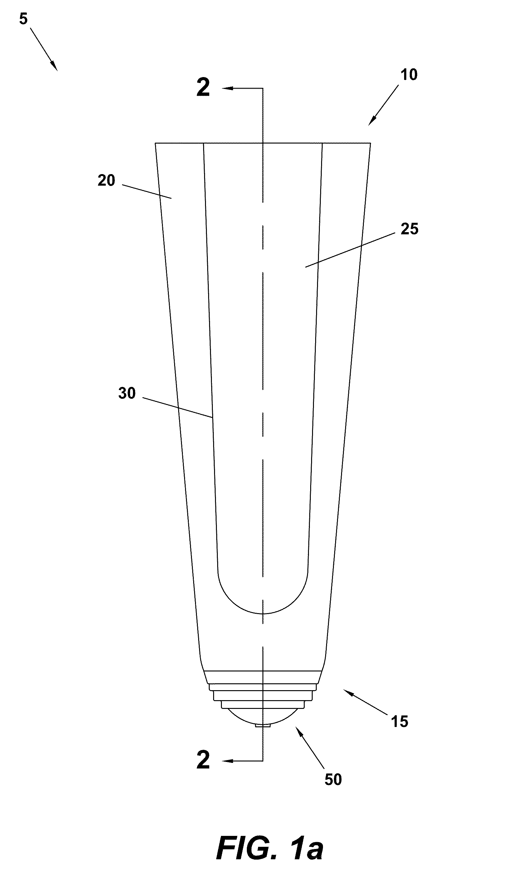
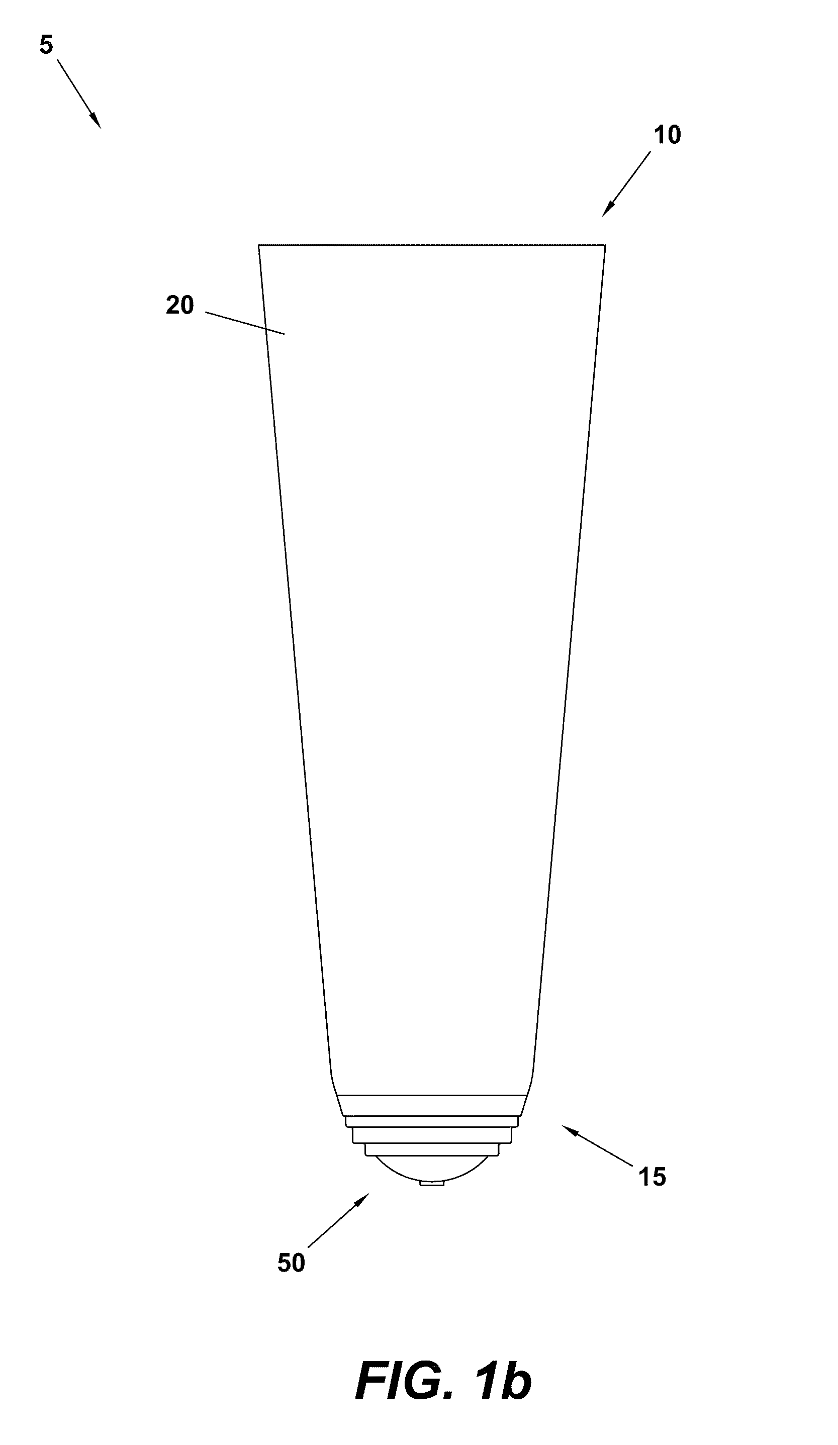
[0032]A first embodiment of a below knee (BK) controlled-stretch prosthetic liner (hereinafter “liner”) 5 of the present invention is depicted in FIGS. 1a-1b and FIG. 2. As shown, the liner 5 includes an open end for permitting insertion of a residual leg, and a closed end 15 opposite the open end.

[0033]As can be best observed in FIG. 2, the interior of the ...


PUM


Abstract

A controlled-stretch prosthetic liner comprising a polymeric material covered with at least a stretch-controlling fabric. Certain liner types, such as below knee (BK) liners, may also include a panel of more stretchable fabric so as to prevent any interference with knee flexion. The polymeric material of the liner may also be used to control liner stretch, such as by adding Kevlar pulp or other materials that increase the strength and reduce the elasticity of the polymeric material and / or by reducing the amount of plasticizer(s) present therein. The stretch-controlling fabric, possibly in conjunction with the polymeric material, acts to limit the longitudinal stretch of the liner while not adversely affecting the radial stretch thereof.

Description

TECHNICAL FIELD[0001]The present invention is directed to a fabric-covered polymeric prosthetic liner designed to function as a standalone interface between an amputee's residual limb and the interior of a prosthetic socket. More particularly, the present invention is directed to such a prosthetic liner having limited and controlled longitudinal stretch characteristics.BACKGROUND[0002]Polymeric prosthetic liners (or “liners”) have become the interface of choice among amputees due to various beneficial characteristics thereof. These characteristics include, for example, comfort, security of suspension, protection of the residual limb, and ease of use. Modern liner technology allows amputees to employ a liner as the sole (stand-alone) interface between their residual limb (which is also commonly referred to as a residuum or amputation stump) and the interior of a prosthetic socket—in contrast to known wool or knit socks and cushioned socks or sheaths that must be worn in multiple laye...

Claims


Application Information

Patent Timeline
Patent Type & Authority Applications(United States)
IPC IPC(8): A61F2/78
CPCA61F2002/7818A61F2/7812
Inventor DODDROE, JEFFREY L.KELLEY, CHRISTOPHER T.ROWE, JR., LARRY GAIL
Owner WILLOWWOOD GLOBAL LLC
Why Eureka
Try Eureka