Identification of Relay Nodes in a Communication Network

Active Publication Date: 2011-08-25
TELEFON AB LM ERICSSON (PUBL)
View PDF6 Cites 66 Cited by
  • Summary
  • Abstract
  • Description
  • Claims
  • Application Information

AI Technical Summary

Benefits of technology

[0015]Knowledge of the relay node identifier enables the donor base station to obtain configuration information for the relay node. Such information is useful because not all relay nodes are expected to have the same hardware and software configurations. The base station may

Problems solved by technology

However, no mechanism currently exists to uniquely identify the relay node to the base station or to provide configuration information for the relay node to the base

Method used


Image

  • Identification of Relay Nodes in a Communication Network
  • Identification of Relay Nodes in a Communication Network
  • Identification of Relay Nodes in a Communication Network

Examples


Example

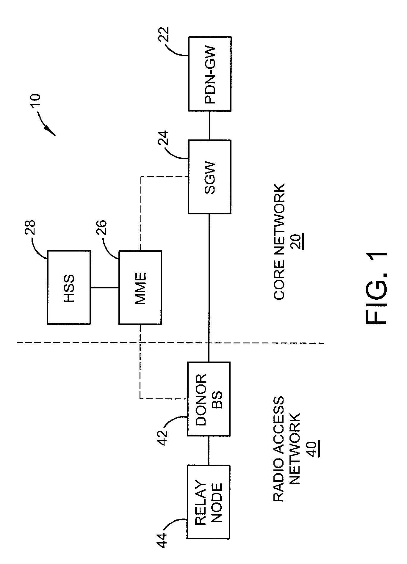
[0026]Referring now to the drawings, FIG. 1 illustrates an exemplary communication network 10 according to one exemplary embodiment of the present invention. For illustrative purposes, the present invention is described in the context of a Long Term Evolution (LTE) network. However, the principles described herein may also be applied to networks based on other communication standards now known or later developed.

[0027]At the highest level, the communication network 10 comprises the core network 20 and the radio access network 40. The core network 20 is responsible for the overall control of the user terminal (not shown) and the establishment of bearers between the user terminal (called user equipment in the LTE standard) and external networks, such as the Internet or other packet data networks (PDNs). The main logical components of the core network 20 comprise the Packet Data Network Gateway (PDN-GW) 22, the Serving Gateway (SGW) 24, the Mobility Management Entity (MME) 26, and the ...


PUM


Abstract

A relay node identified by a unique relay node identifier relays communications between a donor base station and one or more user terminals. The donor base station acquires the relay node identifier during a relay node attach procedure from where the relay node or another node in the core network (e.g., mobile management entity). The donor base station may use the relay node identifier to retrieve configuration information for the relay node. The configuration information may be used to configure the relay node, to perform radio resource management functions, and/or to monitor the performance of the relay node.

Description

TECHNICAL FIELD[0001]The present invention relates generally to communication networks including relay nodes for relaying communications between a donor base station and one or more user terminals and, more particularly, to methods and apparatus for uniquely identifying relay nodes to the donor base station.BACKGROUND[0002]In Long Term Evolution (LTE) systems (3GPP LTE Rel-10), the use of relay nodes has been proposed to improve the coverage and capacity of LTE networks. A relay node may be positioned between a base station (called an eNodeB in the LTE standard) and a user terminal (called user equipment (UE) in the LTE standard) so that transmissions between the base station, referred to herein as the donor base station, and the user terminal are relayed by the relay node. Release 10 of LTE supports Type 1 relay nodes, which appear to the user terminal as a separate base station distinct from the donor base station. The service areas covered by a Type 1 relay nodes, referred to her...

Claims


Application Information

Patent Timeline
IPC IPC(8): G06F15/16
CPCH04B7/155H04B7/2606H04W24/02H04B7/15542H04B7/15507H04L2001/0097H04W28/26H04W84/047H04W8/06H04W60/00H04W88/005H04W88/04
Inventor MILDH, GUNNARMOBERG, PETER
Owner TELEFON AB LM ERICSSON (PUBL)
Why Eureka
Try Eureka