Stator for electric rotating machine

a technology of electric rotating machines and stators, which is applied in the direction of dynamo-electric components, ac commutators, dynamo-electric machines, etc., can solve the problems of difficult to prevent the failure of insulation coatings in stators, and the amplitude of vibration will increase with the distance from stators, so as to prevent the damage of insulating coatings of turn parts

Inactive Publication Date: 2011-09-01
DENSO CORP
View PDF2 Cites 11 Cited by
  • Summary
  • Abstract
  • Description
  • Claims
  • Application Information

AI Technical Summary

Benefits of technology

[0012]With the clearances provided between the overlapping pairs of the parallel parts of the turn portions, it is possible to prevent the turn portions from making contact with each other even if they are caused to vibrate during operation of the electric rotating machine. As a result, it is possible to prevent insulating coats of the turn portions from being damaged due to vibration of the turn portions, thereby ensuring electric insulation between the turn portions.
[0013]Moreover, in general, if the turn portions of the electric wires are caused to vibrate during operation of the electric rotating machine, the amplitude of the vibration will increase with the distance from the stator core. However, by providing the largest clearance between the overlapping pair of the parallel parts which is positioned furthest from the corresponding axial end face of the stator core, it is still possible to reliably prevent the pair of the parallel parts from making contact with each other due to the vibration of the turn portions.

Problems solved by technology

As a result, it may become difficult to prevent insulation failure from occurring in the stator.
Moreover, in general, if the turn portions of the electric wires are caused to vibrate during operation of the electric rotating machine, the amplitude of the vibration will increase with the distance from the stator core.

Method used


Image

  • Stator for electric rotating machine
  • Stator for electric rotating machine
  • Stator for electric rotating machine

Examples


Embodiment Construction

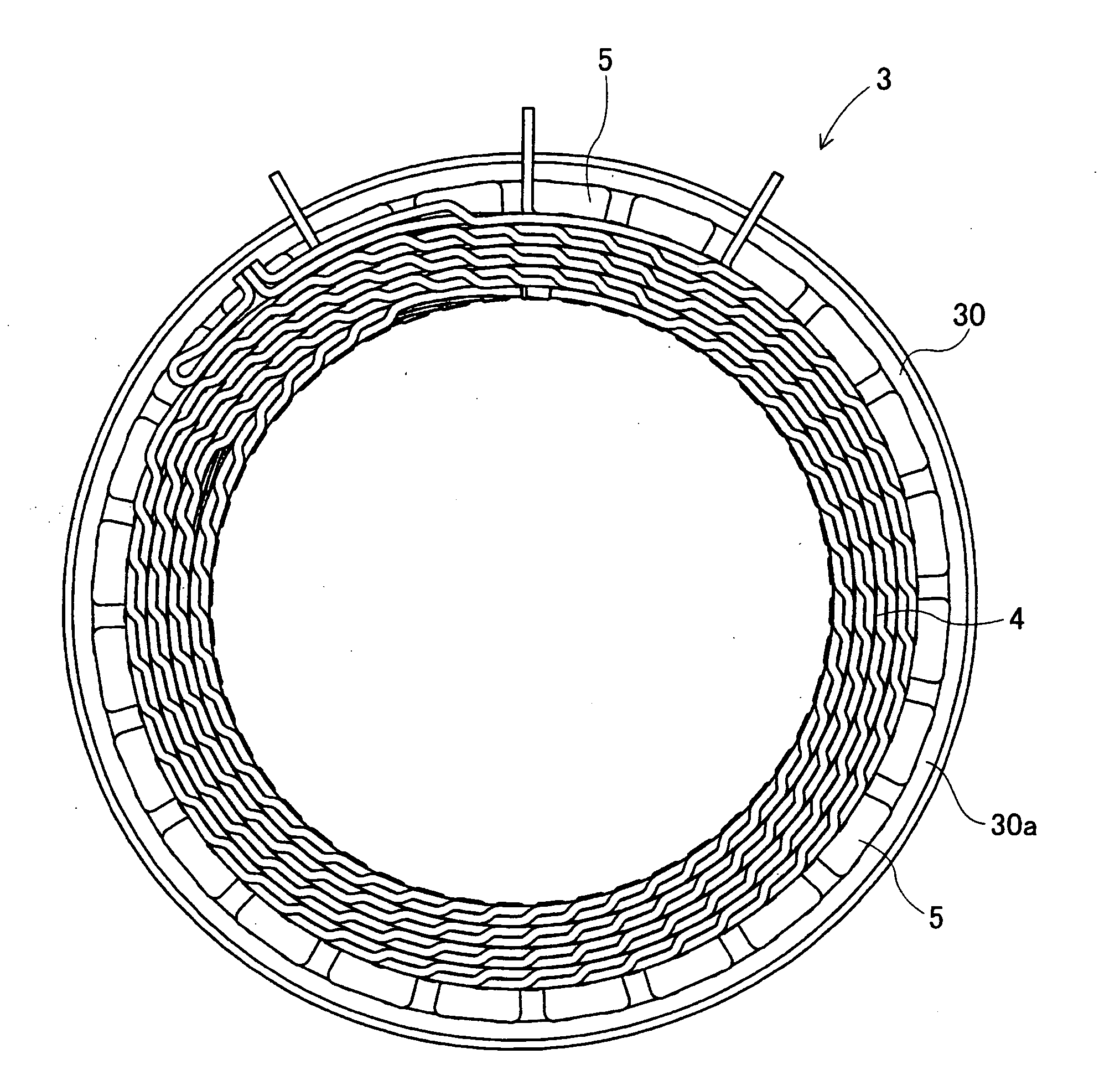
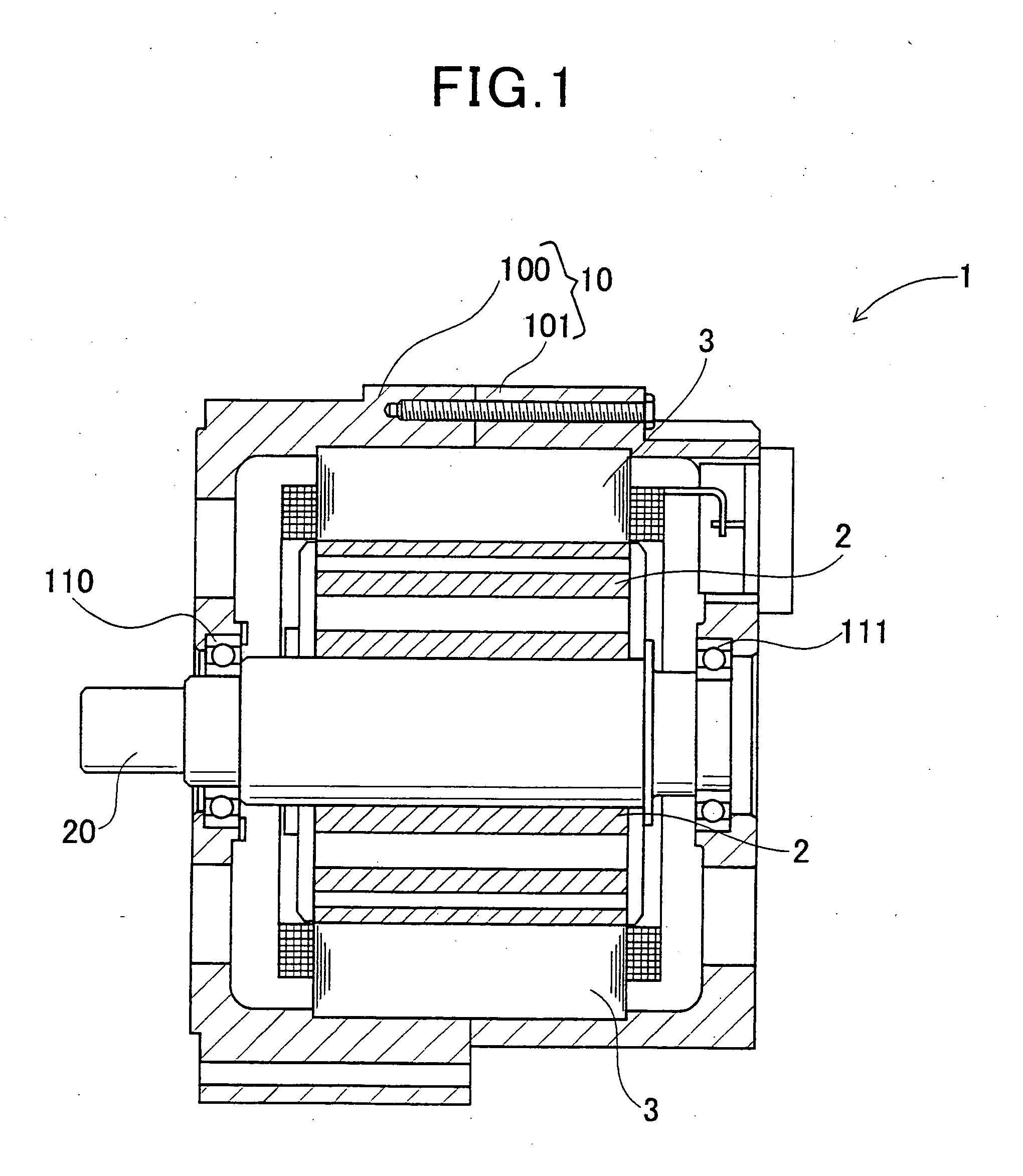
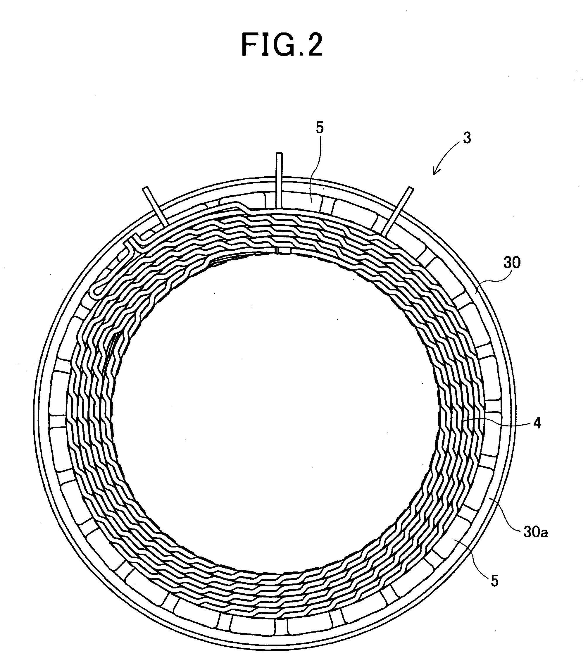
[0031]FIG. 1 shows the overall configuration of an electric rotating machine 1 which includes a stator 3 according to an embodiment of the invention.

[0032]The electric rotating machine 1 is designed for use in a motor vehicle, such as an electric vehicle or a hybrid vehicle, and can function both as an electric motor and as an electric generator.

[0033]As shown in FIG. 1, the electric rotating machine 1 further includes a housing 10 and a rotor 2 in addition to the stator 3. The housing 10 is comprised of a pair of cup-shaped housing pieces 100 and 101 which are jointed together at the open ends thereof. The housing 10 has a pair of bearings 110 and 111 mounted therein, via which a rotating shaft 20 is rotatably supported by the housing 10. The rotor 2 is received in the housing 10 and fixed on the rotating shaft 20. The stator 3 is fixed in the housing 10 so as to surround the radially outer periphery of the rotor 2.

[0034]The rotor 2 includes a plurality of permanent magnets that fo...


PUM


Abstract

A stator includes a stator coil comprised of electric wires each of which has in-slot portions received in slots of a stator core and turn portions located outside the slots to connect the in-slot portions. Each of the turn portions is stepped to have parallel parts that extend substantially parallel to a corresponding axial end face of the stator core. For each pair of the turn portions of the electric wires, which respectively protrude out of an adjacent pair of the slots of the stator core, the parallel parts of one of the turn portions overlap those of the other in the axial direction of the stator core. A clearance provided between one of the overlapping pairs of the parallel parts, which is positioned furthest from the corresponding axial end face of the stator core, is largest among all clearances provided between the overlapping pairs of the parallel parts.

Description

CROSS-REFERENCE TO RELATED APPLICATION[0001]This application is based on and claims priority from Japanese Patent Application No, 2010-42371, filed on Feb. 26, 2010, the content of which is hereby incorporated by reference in its entirety into this application.BACKGROUND[0002]1. Technical Field[0003]The present invention relates to stators for electric rotating machines that are used in, for example, motor vehicles as electric motors and electric generators.[0004]2. Description of the Related Art[0005]Conventionally, there are known stators for electric rotating machines which include a hollow cylindrical stator core and a stator coil mounted on the stator core.[0006]The stator core has a plurality of slots that are formed in the radially inner surface of the stator core and spaced in the circumferential direction of the stator core. The stator coil is comprised of a plurality of electric wires mounted on the stator core. Each of the electric wires includes a plurality of in-slot po...

Claims


Application Information

Patent Timeline
Patent Type & Authority Applications(United States)
IPC IPC(8): H02K3/28
CPCH02K2213/03H02K3/12
Inventor OGAWA, SHINICHIISHIZUKA, ATSUO
Owner DENSO CORP
Why Eureka
Try Eureka