
Control apparatus and liquid ejecting apparatus

Inactive Publication Date: 2011-09-01
SEIKO EPSON CORP
View PDF2 Cites 4 Cited by
  • Summary
  • Abstract
  • Description
  • Claims
  • Application Information

AI Technical Summary

Benefits of technology

[0010]An advantage of some aspects of the invention is that a control apparatus and a liquid ejecting apparatus are provided wherein the waiting time until the start of printing may be shortened and the variation of the printing quality may be suppressed.

Problems solved by technology

However, there is a problem that a heating unit such as heater that heats all flow passages within the recording head cannot be provided and the temperature of the overall recording head is biased even if the heating unit heats the recording head, so that a long heating time is needed to evenly heat the overall recording head to a desired temperature and the waiting time until the start of printing becomes long.
Also, there is a problem that when the temperature of the overall recording head is biased, since insufficiently warmed ink is ejected, high viscosity ink can not ejected with desired ejection characteristics, whereby the printing quality is varied and lowered.
These problems are not only present in the control apparatus that controls the ink jet type recording head but also in a control apparatus of a liquid ejecting head that ejects liquid other than ink.

Method used


Image

  • Control apparatus and liquid ejecting apparatus
  • Control apparatus and liquid ejecting apparatus
  • Control apparatus and liquid ejecting apparatus

Examples


first embodiment

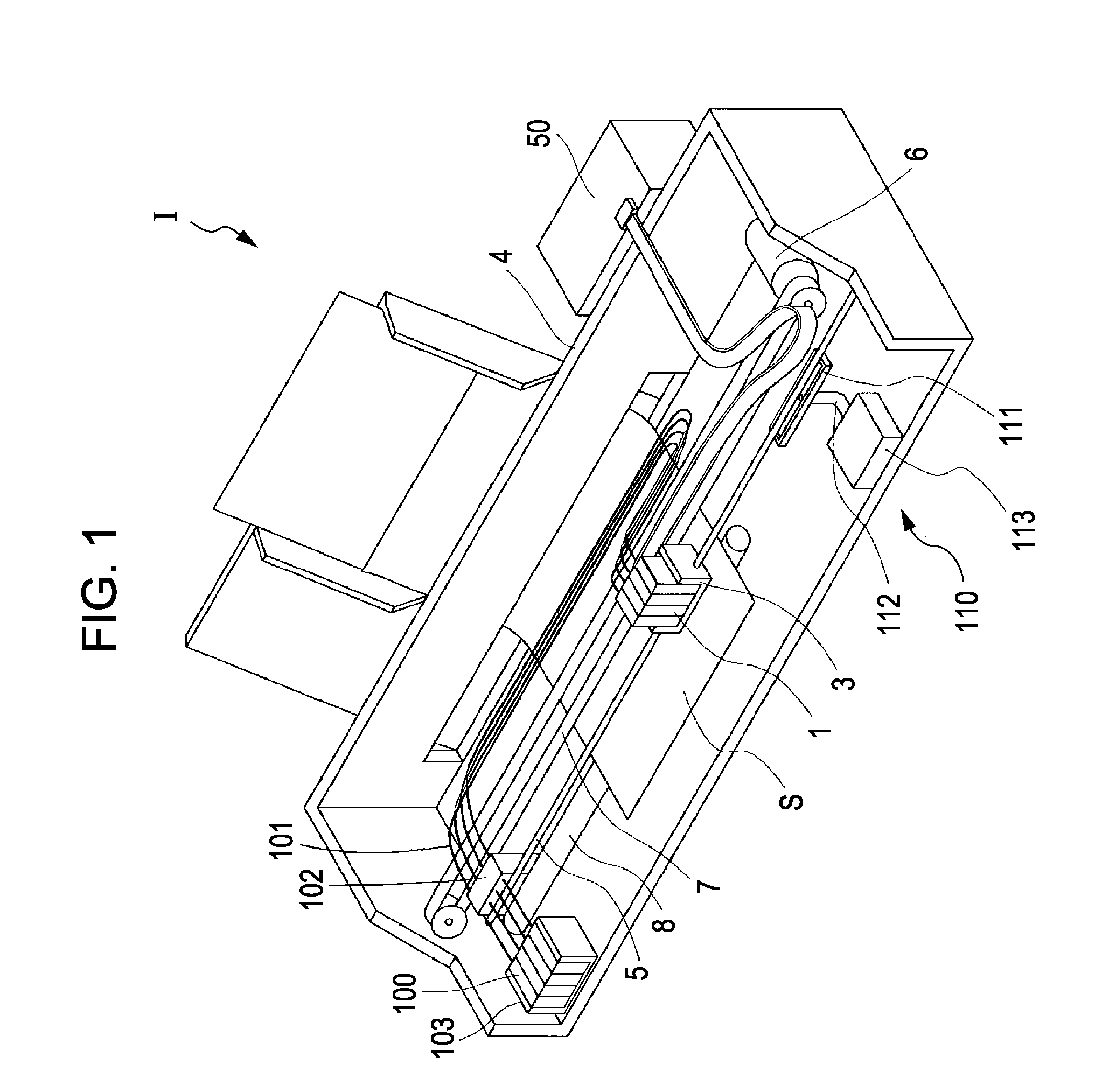
[0029]FIG. 1 is a perspective view showing a schematic configuration of an ink jet type recording apparatus that is an example of a liquid ejecting apparatus of the first embodiment of the invention.

[0030]As shown in FIG. 1, the ink jet type recording apparatus I that is an example of the liquid ejecting apparatus includes an ink jet type recording head 1.

[0031]The ink jet type recording head 1 (hereinafter, also referred to as the recording head 1) is loaded on a carriage 3 and the carriage 3 is disposed to be movable in an axial direction on a carriage shaft 5 that is attached in the apparatus main body 4.

[0032]A driving force of a driving motor 6 is delivered to the carriage 3 through a plurality of gears (not shown) and a timing belt 7 so that the carriage 3 on which the ink jet type recording head 1 is loaded moves along the carriage shaft 5. On the other hand, a platen 8 is disposed in the apparatus main body 4 along the carriage shaft 5 and a recording sheet S that is a recor...

second embodiment

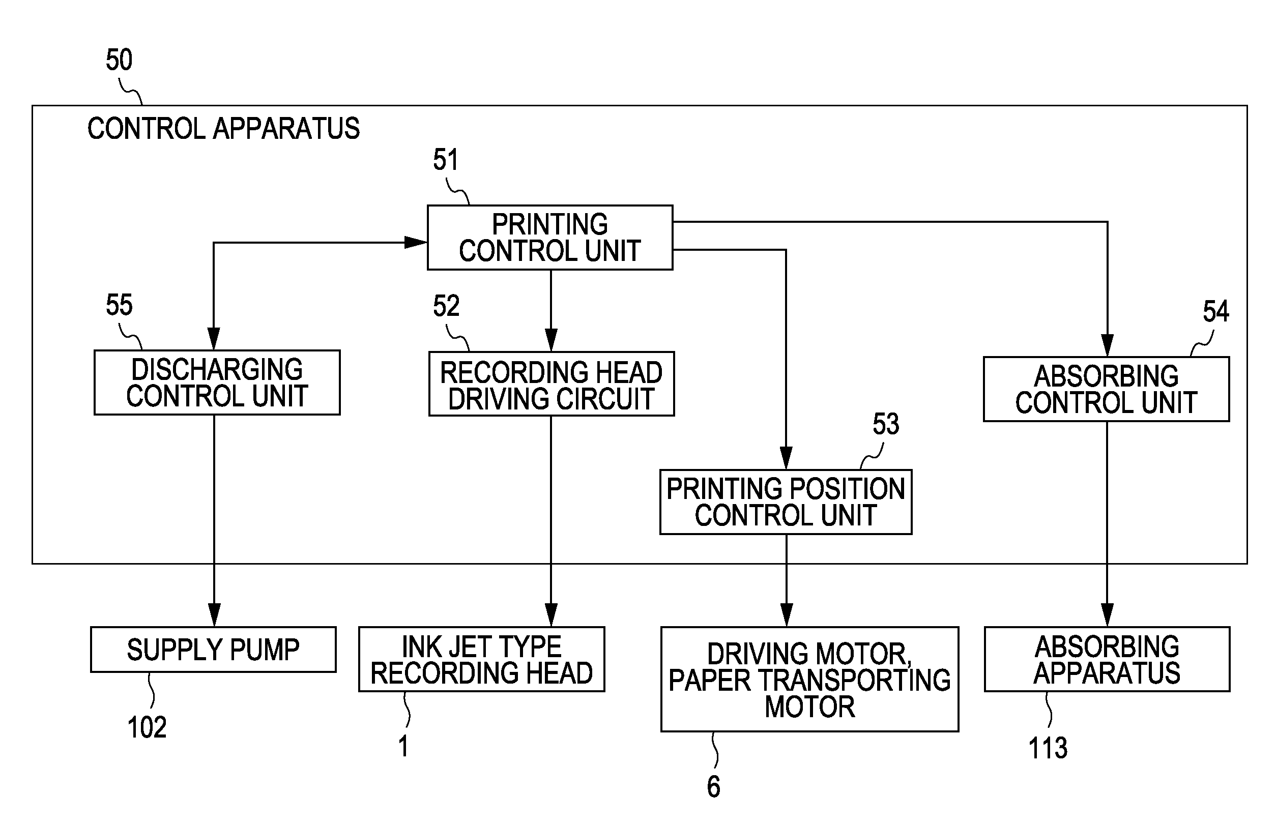
[0063]FIG. 4 is a block diagram schematically showing a configuration of a control apparatus according to a second embodiment of the invention. The constituent members similar to the first embodiment described above are given similar reference numbers thereof, and description thereof is omitted.

[0064]As shown in FIG. 4, a control apparatus 50A of the embodiment includes the printing control unit 51, the recording head driving circuit 52, the printing position control unit 53, the absorbing control unit 54 and a discharge control unit 55A.

[0065]The discharge control unit 55A performs control in which the absorbing operation is performed in the absorbing control unit 54 at a predetermined timing. In other words, the discharge control unit 55A performs the control of the absorbing apparatus 113 to the absorbing control unit 54 at the predetermined timing and the ink is absorbed from the nozzle opening 13 so that the ink within the flow passages is discharged.

[0066]The timing at which t...

third embodiment

[0068]FIG. 5 is a block diagram schematically showing a configuration of the control apparatus according to a third embodiment of the invention. The constituent members similar to the first embodiment described above are given similar reference numbers thereof, and description thereof is omitted.

[0069]As shown in FIG. 5, the control apparatus 50B of the embodiment includes the printing control unit 51, the recording head driving circuit 52, the printing position control unit 53, the absorbing control unit 54 and a discharge control unit 55B.

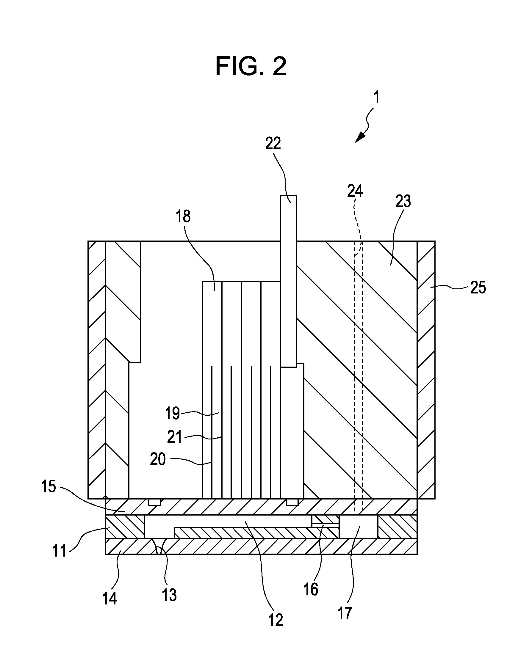
[0070]The discharge control unit 55B of the embodiment drives the piezoelectric element 18 that is the pressure generating unit of the recording head 1 and discharges the ink within the flow passages from the nozzle opening 13. Here, the ink within the flow passages being discharged from the nozzle opening 13 is different from the ink being ejected to the recording sheet S such as in printing, and means for example, that the ink is ejected (disch...


PUM


Abstract

A control apparatus includes a discharge control unit, wherein the discharge control unit controls liquid so that, before a start of printing of which the printing is performed on a printing medium by ejecting a liquid, which is filled and heated within flow passages, from a nozzle opening, the liquid within the flow passages of the liquid ejecting head is discharged from the nozzle opening, and, after the liquid ejecting head is heated to a printing temperature by the heated liquid and the liquid ejecting head reaches the printing temperature, discharging of the liquid from the nozzle opening is stopped.

Description

[0001]The entire disclosure of Japanese Patent Application No: 2010-044791, filed Mar. 1, 2010 are expressly incorporated by reference herein.BACKGROUND[0002]1. Technical Field[0003]The present invention relates to a control apparatus that controls a liquid ejecting head for ejecting liquid from a nozzle opening and a liquid ejecting apparatus that includes the control apparatus.[0004]2. Related Art[0005]As a representative example of the liquid ejecting head that ejects liquid droplets, there is an ink jet type recording head that ejects ink droplets. The ink jet type recording head, for example, includes a nozzle plate in which a nozzle is pierced and disposed, a flow passages forming substrate in which the liquid flow passages including a plurality of pressure generating chambers communicating with the nozzle are formed, and a pressure generating unit that is formed in one side of the flow passages forming substrate.[0006]Recently, demand has increased for printing not only on a ...

Claims


Application Information

Patent Timeline
IPC IPC(8): B41J29/38
CPCB41J2/04528B41J2/04551B41J2/04553B41J2202/08B41J2/0458B41J2/04581B41J2/04588B41J2/04563
Inventor UEZAWA, HARUHISA
Owner SEIKO EPSON CORP
Features
  • Generate Ideas
  • Intellectual Property
  • Life Sciences
  • Materials
  • Tech Scout
  • Unparalleled Data Quality
  • Higher Quality Content
  • 60% Fewer Hallucinations
Learn More