Imaging lens, optical apparatus including imaging lens and method for manufacturing imaging lens

a manufacturing method and imaging lens technology, applied in the field of imaging lens, can solve the problems of large amount of lens extension, difficult to control fluctuations of spherical aberration and curvature of field, and difficult to build up a structure of the lens barrel, so as to achieve less change in overall length

Active Publication Date: 2011-09-01
NIKON CORP
View PDF12 Cites 13 Cited by
  • Summary
  • Abstract
  • Description
  • Claims
  • Application Information

AI Technical Summary

Benefits of technology

[0030]In the third aspect of the present invention, it is preferable that the following step is further included: moving at least one of said second lens group and said third lens group so as to narrow a distance between said second lens group and said third lens group upon focusing on the near-distance object point from the infinite-distance object point.
[0035]It is feasible to provide, when configuring an imaging lens, an optical apparatus including the imaging lens and a method for manufacturing the imaging lens in the way described above, a downsized imaging lens suited to an imaging apparatus such as a single lens reflex camera, having a less of change in overall length and optimal to driving the intra-lens-barrel motor.

Problems solved by technology

Further, in the case of desiring a length of a lens barrel to be kept short in an infinite-distance object point focusing state and desiring a small-sized and compact lens barrel as well, a large amount of lens extension is hard to build up a structure of the lens barrel.
Moreover, in the case of reducing the moving amount of particularly the first lens group while accelerating the downsizing on the extension of the prior arts, it is difficult to control fluctuations of spherical aberration and curvature of field due to focusing, and there is a room for further improvements.

Method used


Image

  • Imaging lens, optical apparatus including imaging lens and method for manufacturing imaging lens
  • Imaging lens, optical apparatus including imaging lens and method for manufacturing imaging lens
  • Imaging lens, optical apparatus including imaging lens and method for manufacturing imaging lens

Examples


example 1

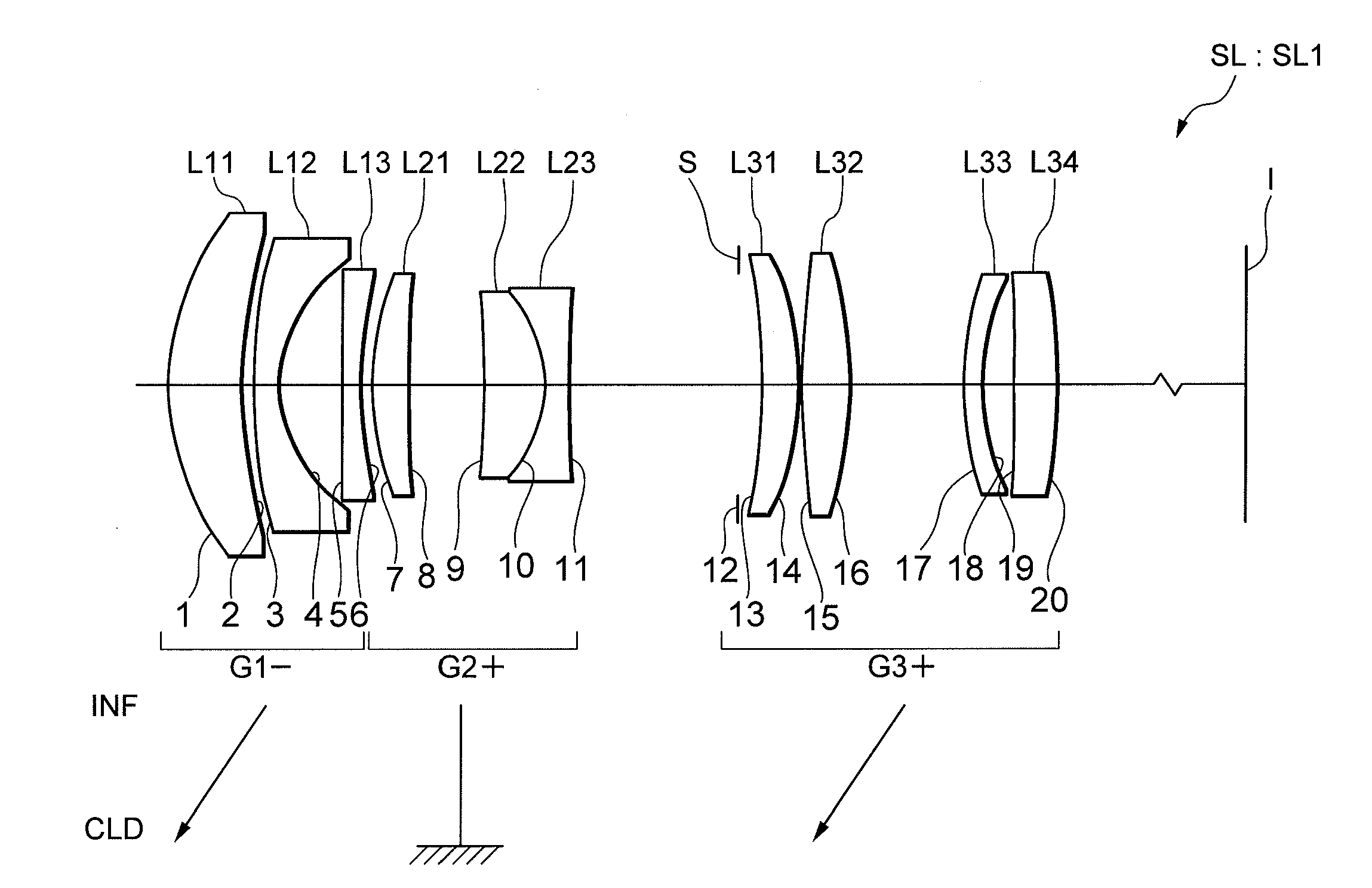
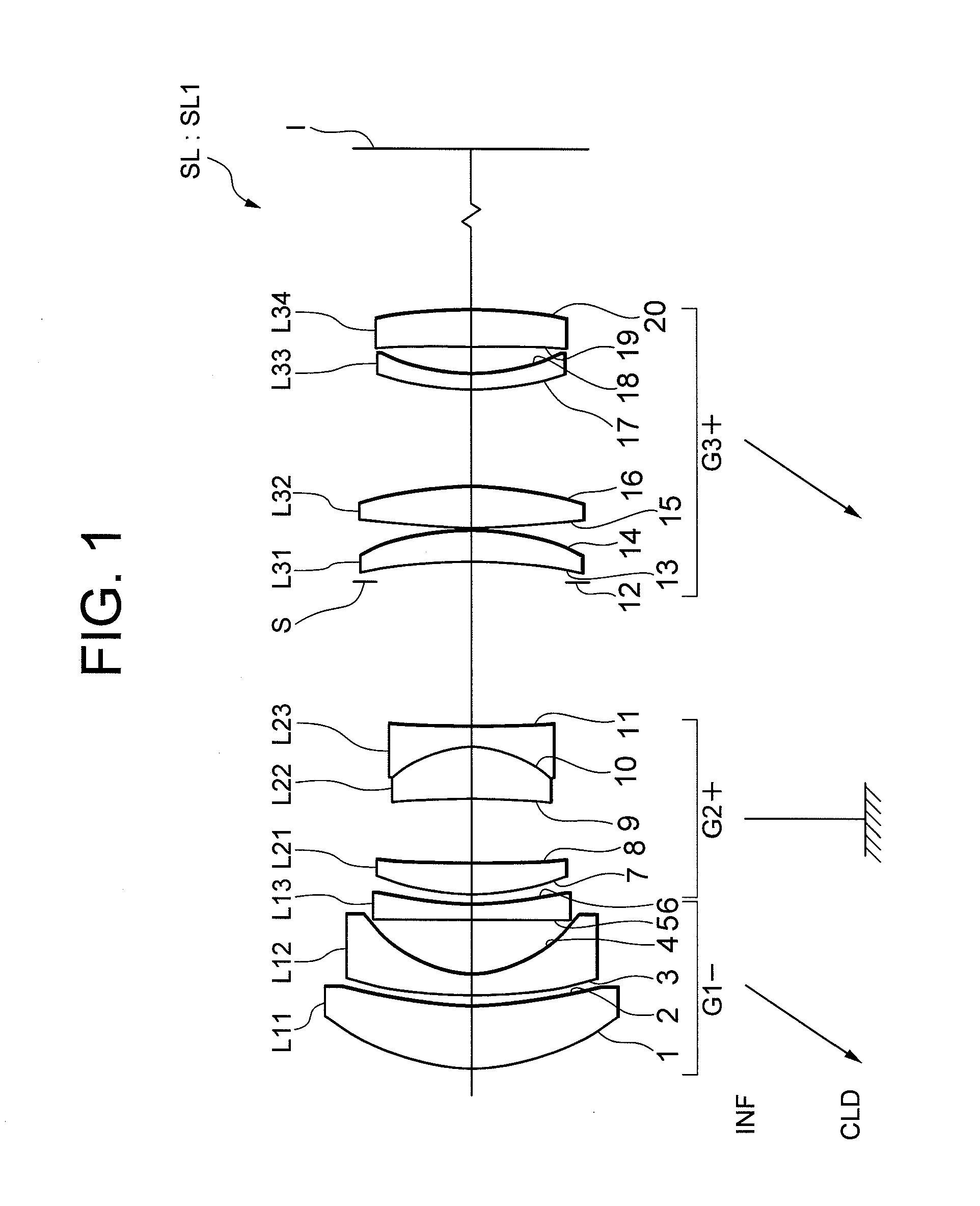
[0080]FIG. 1 is a view showing a configuration of an imaging lens SL1 according to Example 1. In the imaging lens SL1 in FIG. 1, a first lens group G1 is composed of, in order from an object side, a positive meniscus lens L11 with a convex surface directed to the object side, a negative meniscus lens L12 with a convex surface directed to the object side and a biconcave lens L13 having an aspherical surface on the image side. Further, a second lens group G2 is composed of, in order from the object side, a positive meniscus lens L21 with a convex surface directed to the object side and a cemented positive lens constructed by a positive meniscus lens L22 having an aspherical surface on the object side cemented with a biconcave lens L23. Moreover, a third lens group G3 is composed of, in order from the object side, an aperture stop S, a positive meniscus lens L31 with a convex surface directed to the image side, a biconvex lens L32, a negative meniscus lens L33 with a convex surface dir...

example 2

[0085]FIG. 3 is a view showing a configuration of an imaging lens SL2 according to Example 2. In the imaging lens SL2 shown in FIG. 3, a first lens group G1 is composed of, in order from an object side, a positive meniscus lens L11 with a convex surface directed to the object side, a negative meniscus lens L12 with a convex surface directed to the object side and a biconcave lens L13 having an aspherical surface on the image side. Further, a second lens group G2 is composed of, in order from the object side, a biconvex lens L21 and a cemented negative lens constructed by a positive meniscus lens L22 having an aspherical surface on the object side cemented with a biconcave lens L23. Moreover, a third lens group G3 is composed of, in order from the object side, an aperture stop S, a positive meniscus lens L31 with a convex surface directed to the image side, a biconvex lens L32, a negative meniscus lens L33 with a convex surface directed to the object side and a positive meniscus lens...

example 3

[0089]FIG. 5 is a view showing a configuration of an imaging lens SL3 according to Example 3. In the imaging lens SL3 in FIG. 5, a first lens group G1 is composed of, in order from an object side, a positive meniscus lens L11 with a convex surface directed to the object side, a negative meniscus lens L12 with a convex surface directed to the object side and a biconcave lens L13 having an aspherical surface on the image side. Further, a second lens group G2 is composed of, in order from the object side, a positive meniscus lens L21 with a convex surface directed to the object side and a cemented negative lens constructed by a positive meniscus lens L22 having an aspherical surface on the object side cemented with a biconcave lens L23. Moreover, a third lens group G3 is composed of, in order from the object side, an aperture stop S, a positive meniscus lens L31 with a convex surface directed to the image side, a biconvex lens L32, and a negative meniscus lens L33 with a convex surface...


PUM


Abstract

An imaging lens SL mounted in a digital single lens reflex camera 1 is composed of, in order from an object side, a first lens group G1 having negative refractive power, a second lens group G2 having positive refractive power, and a third lens group G3 having positive refractive power, wherein upon focusing on a near-distance object point from an infinite-distance object point, at least one of the first lens group G1 and the second lens group G2 is moved so as to change a distance between the first lens group G1 and the second lens group G2, and the imaging lens satisfies a given conditional expression, thereby providing a downsized imaging lens suited to an imaging apparatus such as a single lens reflex camera, having a less of change in overall length and optimal to driving an intra-lens-barrel motor.

Description

[0001]The disclosure of the following priority application is herein incorporated by reference:[0002]Japanese Patent Application No. 2010-042006 filed on Feb. 26, 2010.BACKGROUND OF THE INVENTION[0003]1. Field of the Invention[0004]The present invention relates to an imaging lens, an optical apparatus including the imaging lens, and a method for manufacturing the imaging lens.[0005]2. Related Background Art[0006]A macro (micro) lens has been proposed, which is capable of focusing from an infinite-distance object point up to a photographic life-size magnification (shooting magnification=−1.0) (refer to, e.g., Japanese Patent Application Laid-Open No. 07-181390).[0007]According to the prior art shown by Japanese Patent Application Laid-Open No. 07-181390, the imaging lens could not be used for an interchangeable lens equipped with an intra-lens-barrel motor, which is conceived as a mainstream type of lens at the present, due to a large moving amount of especially a first lens group am...

Claims


Application Information

Patent Timeline
Patent Type & Authority Applications(United States)
IPC IPC(8): G02B15/14
CPCG02B15/173G02B15/143507
Inventor SATO, HARUOMURATANI, MAMI
Owner NIKON CORP
Why Eureka
Try Eureka