[0003]It is, therefore, an object of the present invention is to provide a pump unit that will make it possible to avoid any destruction to the pump unit when transporting the same and, moreover, that will permit an especially simple installation of the pump unit in a housing.
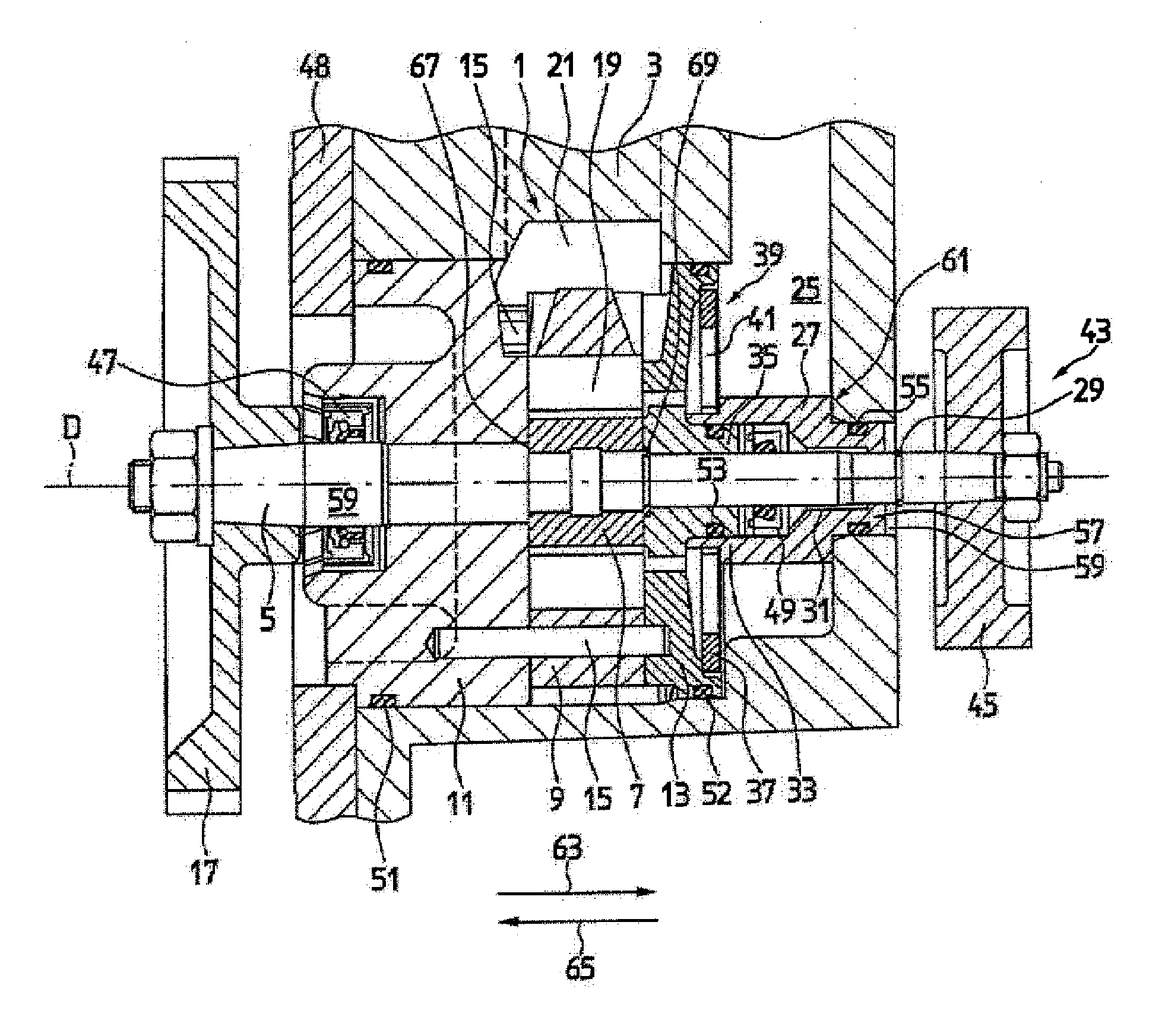
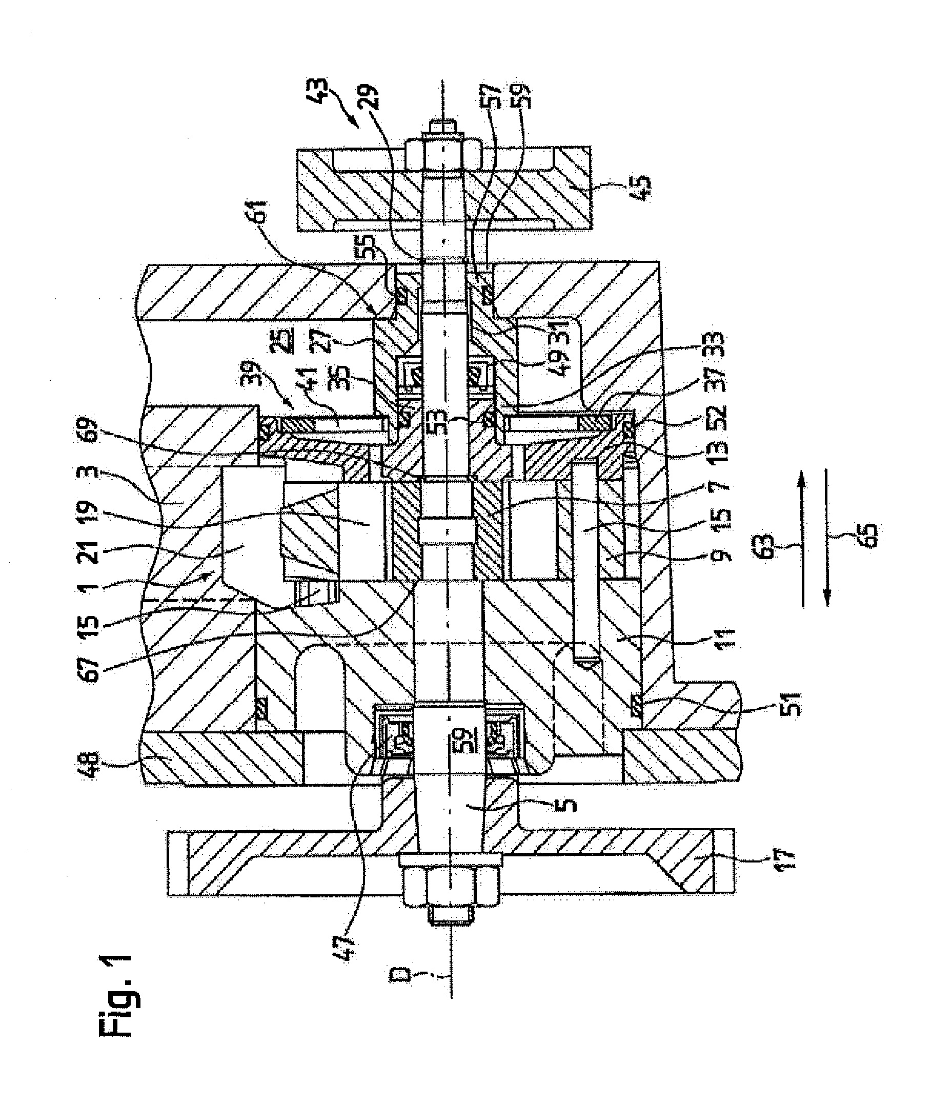
[0004]The present invention provides a pump unit having no dedicated housing, comprising a drive shaft; a rotor that cooperates with the drive shaft for accommodating vanes; a contour ring surrounding the rotor; a first and a second side plate, which are configured to the side of the contour ring. It is distinguished in that a sleeve is provided which is movably supported on the drive shaft and is located downstream of the second side plate in the axial direction of the pump unit. It also has the feature whereby a securing element is provided for axially securing the sleeve on the drive shaft, thereby preventing the pump unit from coming apart during shipment. Moreover, the pump unit features a spring element which preloads the second side plate against the transmission housing, the spring element being a fixed component of the pump unit. In this manner, the individual elements of the pump unit are held securely together even during transporting of the same and, moreover, it is ensured that the second side plate engages securely on the contour ring when the pump is assembled in a housing, thereby avoiding problems associated with starting up the pump unit. Another
advantage of the pump unit provided here is the particularly flexible use thereof in that the spring element makes it possible to compensate for tolerances in the event of dimensional variations.
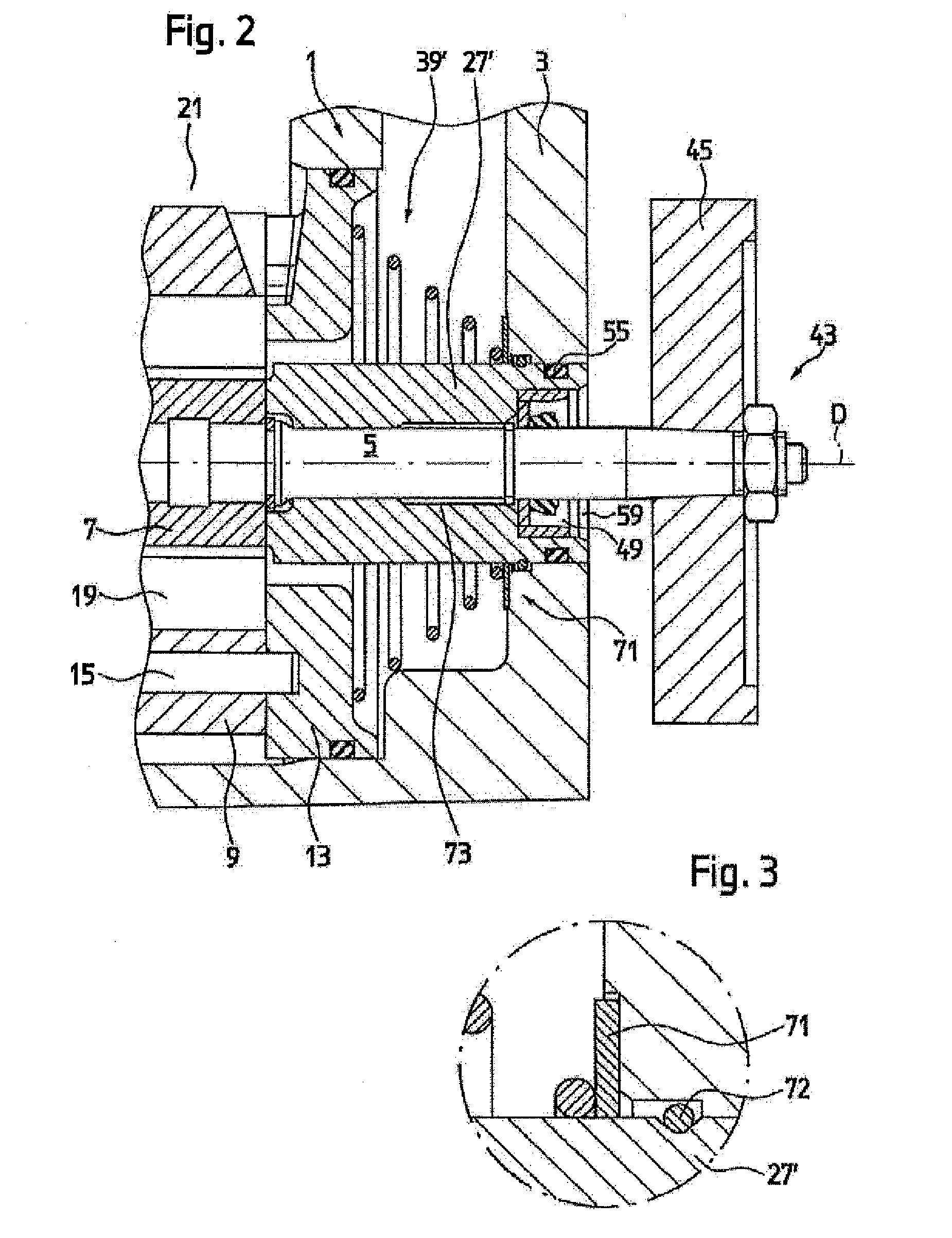
[0005]One exemplary embodiment of the present invention is especially preferred that has the feature whereby the securing element is a locking ring that cooperates with the drive shaft. This provides for a reliable axial securing of the sleeve on the drive shaft, so that the individual components of the pump unit are not able to slip from the drive shaft during shipment. This eliminates the need for a pump housing for transporting the pump unit. It is thus possible to transport the pump unit as a compact unit without employing additional measures for securing the same.
[0007]One exemplary embodiment of the present invention is also preferred which has the feature whereby the spring element is designed as a disk spring that is braced on one side against the second side plate and, on the other side, against the sleeve. The sleeve is then preferably supported, in turn, via a collar on the transmission housing, so that the spring element preloads the second side plate against the housing, in particular, against the transmission housing. This exemplary embodiment is particularly advantageous when the sleeve is movably supported in the axial direction on an extension of the second side plate. In this manner, when the pump is installed, a secure engagement of the pump components may be ensured.
[0009]Another preferred exemplary embodiment of the present invention provides that the sleeve and the second side plate are formed in one piece. In this exemplary embodiment as well, a securing element is preferably used to axially secure the sleeve. The spring element is designed as a compression spring, preferably as a
coil spring, in particular as a frustoconical
coil spring that is braced on one side against the second side plate and, on the other side, against a supporting device which is movably supported on the sleeve. The supporting device may be designed in any given manner, for example as a disk. It is also conceivable for a groove to be introduced into the sleeve and for one end of the
coil spring to be displaceably positioned within the groove. In this specific embodiment, it is also important that the side plate be preloaded against the housing, so that, when the pump unit is assembled in a housing, a secure engagement of the individual components relative to one another is ensured, thereby avoiding the difficulties associated with starting up the pump unit.
[0011]One exemplary embodiment of the present invention is also preferred that has the feature whereby a
shaft collar is provided for axially securing the first pressure plate. In this manner, all elements of the pump unit are securely supported on the drive shaft and are not able to fall off of the same. Thus, the pump unit may be safely transported without the need for any additional measures for securing the same.

