Ballistic panels and method of making the same

a technology of ballistic panels and ballistic materials, applied in the field of ballistic panels, can solve the problems of reducing comfort and flexibility, reducing the ability of water or other liquids to stop bullets, and reducing the stiffness of the resulting ballistic material, so as to achieve the effect of improving ballistic performance and waterproofness

Inactive Publication Date: 2011-09-08
WL GORE & ASSOC INC
View PDF16 Cites 20 Cited by
  • Summary
  • Abstract
  • Description
  • Claims
  • Application Information

AI Technical Summary

Benefits of technology

[0007]A ballistic panel is described that comprises a ballistic-resistant component and a cover that comprises a laminate comprising (i) a substrate layer, and (ii) an inner bonding layer, wherein the cover is bonded to at least one surface of the ballistic-resistant component by the inner bonding layer of the laminate. The cover further comprises a second material layer adjacent the opposite surface of the ballistic-resistant component to which the laminate is bonded. The second material is bonded to the laminate around the perimeter of the ballistic resistant component forming a perimeter seal beyond the edge of the ballistic-resistant component. A method for making the ballistic panel is also described. Ballistic panels are described, for example, that report durable waterproofness and improved ballistic performance.

Problems solved by technology

Ballistic materials saturated with a significant amount of water or other liquids may lose a significant portion of the ability to stop bullets.
While somewhat effective at reducing water saturation, this approach results in stiffening of the resulting ballistic material, reducing comfort and flexibility.
Another approach is to cover the ballistic material with a waterproof component; however, non-breathable waterproof materials increase the thermal burden to the wearer, decreasing wearer comfort.
In addition, any significant moisture from the manufacturing environment, or significant water ingress resulting from unknown pinholes or cracks developed through normal wear, may get trapped within the non-breathable cover and potentially degrade ballistic performance.

Method used


Image

  • Ballistic panels and method of making the same
  • Ballistic panels and method of making the same
  • Ballistic panels and method of making the same

Examples


example 1

[0099]A ballistic panel was formed comprising Ballistic-resistant Component 1 (BRC1) and Laminate 1 (L1) in the following manner.

[0100]Two pieces of L1 were cut to dimensions of about 24″ long by 20″ wide and placed on a flat surface. The woven outer fabric layer of a first piece of laminate was facing down and the TPU inner layer was facing up. BRC1 was removed from its original nylon cover (which was discarded) and placed strike face side up in the center of L1 on the TPU inner layer. The strike face side was labeled by the ballistic-resistant component manufacturer. All loose edge fibers of BRC1 were trimmed and removed or tucked within BRC1 with a brush or fingertips. A second piece of L1 was placed over the BRC1 on a side opposite the strike face with the TPU inner layer facing towards BRC1, and the edges and corners of both L1 pieces extending beyond the perimeter of BRC1 were aligned, forming a BCR1 / L1 lay-up.

[0101]The BRC1 / L1 lay-up was placed on a silicone rubber pad having...

example 2

[0111]A ballistic panel was formed comprising Ballistic-resistant Component 1 (BRC1) and Laminate 1 (L1) in the following manner.

[0112]A BRC1 / L1 lay-up was prepared according to the method of Example 1.

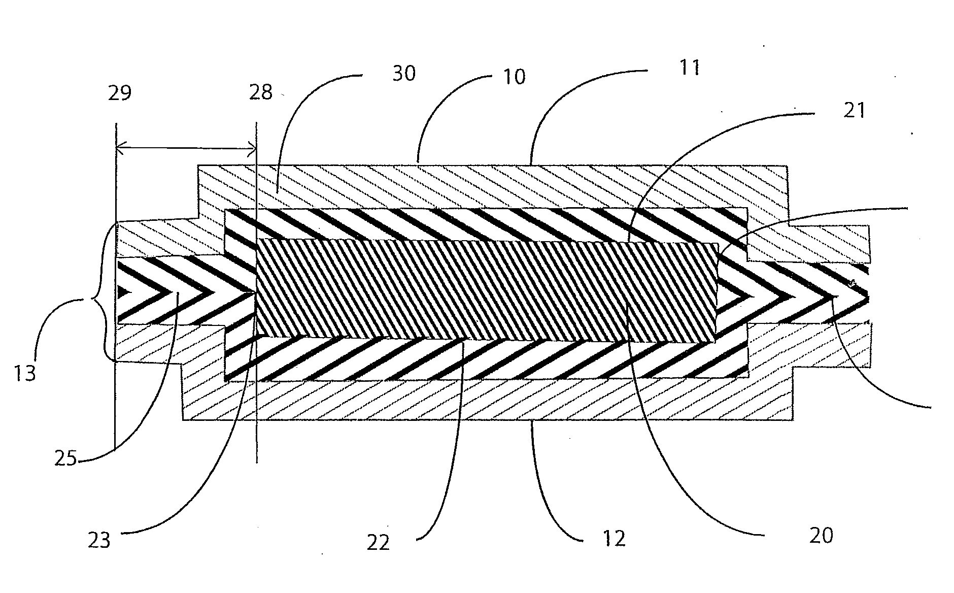
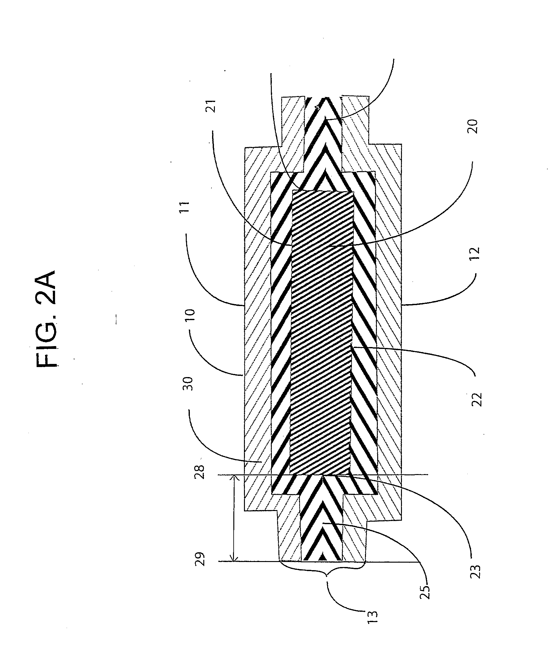
[0113]A model type 21st Century Sealing Iron (Coverite, made in Taiwan) set to about 380° F. was hand pressed to the top surface of L1 woven outer fabric layer and moved at a rate of about 12″ / min so as to melt the TPU inner bonding layer bonding it to the BRC1 first surface producing a bond (24) width of about 3 mm. A bond in the pattern of a perpendicular grid with spacing of about 1.5″ was produced across the entire ballistic panel surface as illustrated in FIG. 10. This process was repeated so that the TPU inner bonding layer of the second piece of L1 was adhered to the second surface of BRC1, in this manner. The TPU inner layer of L1 was bonded uniformly over approximately 15% of the surface of BRC1.

The panel cover L1 was trimmed to the approximate shape of the BRC1 with about 1″...

example 3

[0116]A ballistic panel was formed comprising ballistic-resistant component 2 (BRC2) and Laminate 1 (L1) in the following manner.

[0117]A BRC2 / L1 lay-up was prepared according to the method of Example 1, except that the BRC1 of Example 1 was substituted with BRC2.

[0118]The BRC2 / L1 lay-up was placed on a silicone rubber pad as described in Example 1 and loaded onto the heat press as described in Example 1, so that the surface of the BRC2 labeled ‘strike face’ was facing up. The lay-up was covered with a piece of 6 mil Brown Teflon®Cloth (Apparel Machinery & Supply Co., Philadelphia, Pa.) approximately 48″ by 30″ to prevent adhesive sticking to the platens, and heat pressed using the settings as described in Example 1.

[0119]The lower platen then released from the upper platen, was horizontally unloaded and the Teflon® Cloth removed. The outer panel cover of the lay-up was labeled “strike face” and the lay-up was flipped 180 degrees so that the side of the BRC2 containing Dyneema® was f...


PUM

PropertyMeasurementUnit
thicknessaaaaaaaaaa
widthaaaaaaaaaa
thicknessaaaaaaaaaa

Abstract

A ballistic panel is described that comprises a ballistic-resistant component and a cover that comprises a laminate comprising (i) a substrate layer and (ii) an inner bonding layer. The cover is bonded to at least one surface of the ballistic-resistant component by the inner bonding layer of the laminate, and is bonded around the perimeter of the ballistic resistant component to form a perimeter seal. A method for making the ballistic panel is also described.

Description

BACKGROUND[0001]1. Field of the Invention[0002]A cover for a flexible ballistic resistant component is described. Ballistic panels comprising a cover and a flexible ballistic-resistant component are also described. The cover comprises a laminate that is sealed around the perimeter and to the surface of the ballistic-resistant component that secures the cover to the ballistic-resistant component.[0003]2. Description of Related Art[0004]Ballistic materials saturated with a significant amount of water or other liquids may lose a significant portion of the ability to stop bullets. One approach to protecting against water saturation is to treat each layer of the ballistic material with a waterproofing agent. While somewhat effective at reducing water saturation, this approach results in stiffening of the resulting ballistic material, reducing comfort and flexibility. Another approach is to cover the ballistic material with a waterproof component; however, non-breathable waterproof materi...

Claims


Application Information

Patent Timeline
Patent Type & Authority Applications(United States)
IPC IPC(8): F41H5/04B32B37/06B32B37/00
CPCB32B37/00B32B37/06Y10T156/10F41H5/0478F41H5/04Y10T442/2623Y10T442/2615B32B27/12B32B5/024B32B27/40B32B5/022B32B2262/0269B32B2262/0253B32B2307/7265B32B2262/0261B32B5/26B32B2309/12
Inventor LAMPO, STEVEN MICHAELBIRO, ANDREA
Owner WL GORE & ASSOC INC
Why Eureka
Try Eureka