Gas sensor element, gas sensor and control system of gas sensor

a technology of gas sensor and control system, which is applied in the direction of instruments, scientific instruments, measurement devices, etc., can solve the problems of complex construction of sensor elements and considerable changes in resistance values of the same, and achieve the effect of improving the effect of detecting resistance values and easy obtaining resistance values of compensating resistors

Active Publication Date: 2011-09-08
NGK SPARK PLUG CO LTD
View PDF7 Cites 15 Cited by
  • Summary
  • Abstract
  • Description
  • Claims
  • Application Information

AI Technical Summary

Benefits of technology

[0016]In the first embodiment, the cell may be an oxygen generating cell that generates oxygen when a constant current is forced to flow through the cell. In this case, due to flowing of the constant current through the oxygen generating cell, the resistance value of the compensating resistor is easily obtained by forcing the constant current to flow through the compensating resistor.
[0017]In the first embodiment, the compensating resistor may be covered with a protecting layer to protect the compensating resistor from surrounding gas. Due to provision of the such protecting layer, undesired contact between the compensating resistor and the surrounding gas is completely blocked. With such protecting layer, the compensating resistor is protected from being affected by the temperature of the gas, which improves the effect of detecting the resistance value of the compensating resistor.
[0018]In the first embodiment, the compensating resistor may be trimmed to have an adjustable resistance value that is reflected by the correction information. Usage of trimming for adjusting the resistance value of the compensating resistor brings about easiness with which fine adjustment of the resistance value is carried out.
[0019]In a second embodiment of the present invention, there is provided a gas sensor...

Problems solved by technology

However, if the above-mentioned measures are simply applied to a gas sensor element that comprises a cell including a solid electrolyte body and a pair of electrodes having the solid electrolyte body put therebetween, temperature changes of the solid electrolyte body bring abo...

Method used


Image

  • Gas sensor element, gas sensor and control system of gas sensor
  • Gas sensor element, gas sensor and control system of gas sensor
  • Gas sensor element, gas sensor and control system of gas sensor

Examples


Embodiment Construction

[0029]In the following, the present invention will be described in detail with reference to the accompanying drawings.

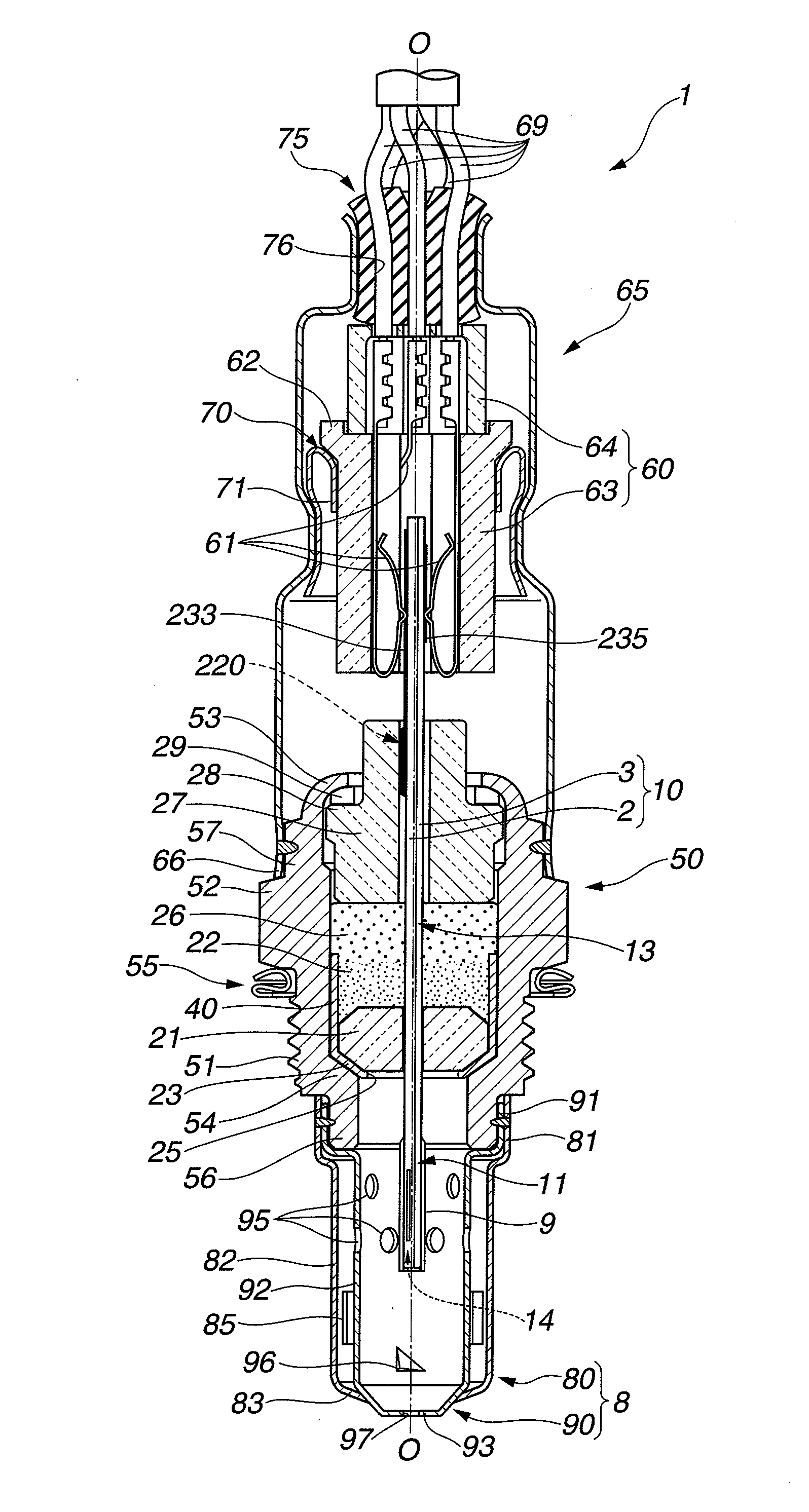
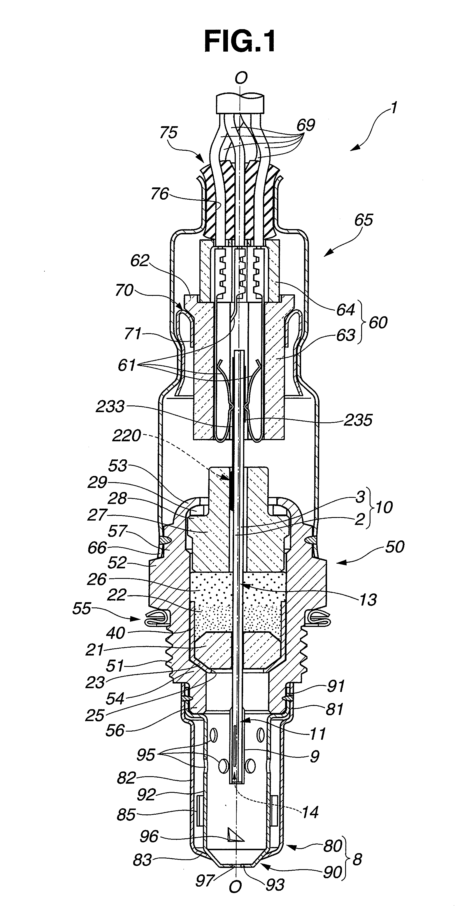
[0030]Referring to FIGS. 1 to 4, there is shown a gas sensor 1 according to the present invention. Actually, the gas sensor 1 shown is of a type that senses oxygen concentration.

[0031]It is to be noted that in FIGS. 1, 2 and 4, an axial direction “O” of the gas sensor 1 is represented by a vertical direction and in FIG. 3, the axial direction “O” is represented by a horizontal direction. In FIGS. 1 and 2, the axial direction “O” is depicted by an alternate long and short dash line, and in FIGS. 3 and 4, the axial direction “O” is indicated by an arrow. In FIGS. 1, 2 and 4, a leading portion of the gas sensor 1 is shown at a lower part, and in FIG. 3, the leading portion of the gas sensor 1 is placed at a right part. Thus, an end portion of the gas sensor 1 is placed at a part opposite to the above-mentioned part in each figure.

[0032]Referring back to FIG. 1, the gas ...


PUM


Abstract

In order to compensate for variation in output of sensor elements 10, there is provided a compensating resistor 220 that has a resistance value reflected by correction information. The resistor 220 is connected in parallel with a VS cell 245 through paired electrode leads 236 and 237 and paired electrode pads 232 and 233. The paired electrode leads 236 and 237 are placed at a position electrically isolated from solid electrolyte substrates 120 and 140.

Description

BACKGROUND OF THE INVENTION[0001]1. Field of the Invention[0002]The present invention relates to a gas sensor element and a gas sensor for detecting the concentration of a specific gas in gaseous environment, and a control system of the gas sensor.[0003]2. Description of the Related Art[0004]Hitherto, for detecting the concentration of oxygen in the exhaust gas from an internal combustion engine of a motor vehicle, various types of gas (viz., oxygen) sensors have been proposed and put into practical use. Some of them are of a type that uses a gas sensor element which comprises a cell including a solid electrolyte body of zirconia or the like and a pair of electrodes having the solid electrolyte body intimately put therebetween. The concentration of a specified gas is detected based on current flowing between the electrodes through the solid electrolyte body.[0005]As is known, the gas sensor elements are those that tend to show variations in output caused by variations in production....

Claims


Application Information

Patent Timeline
IPC IPC(8): G01N27/417
CPCG01N27/417G01N27/4175
Inventor YOSHIDA, SHINMORI, SHIGEKIKAWAI, TAKESHIINAGAKI, HIROSHIOYA, SEIJIMORI, KENTARO
Owner NGK SPARK PLUG CO LTD
Why Eureka
Try Eureka