

Flat panel display integrated with touch screen panel
- Summary
- Abstract
- Description
- Claims
- Application Information
AI Technical Summary
Benefits of technology
Problems solved by technology
Method used
Image

Examples
Embodiment Construction
[0024]Reference will now be made in detail to the present embodiments of the present invention, examples of which are illustrated in the accompanying drawings, wherein like reference numerals refer to the like elements throughout. The embodiments are described below in order to explain the present invention by referring to the figures.
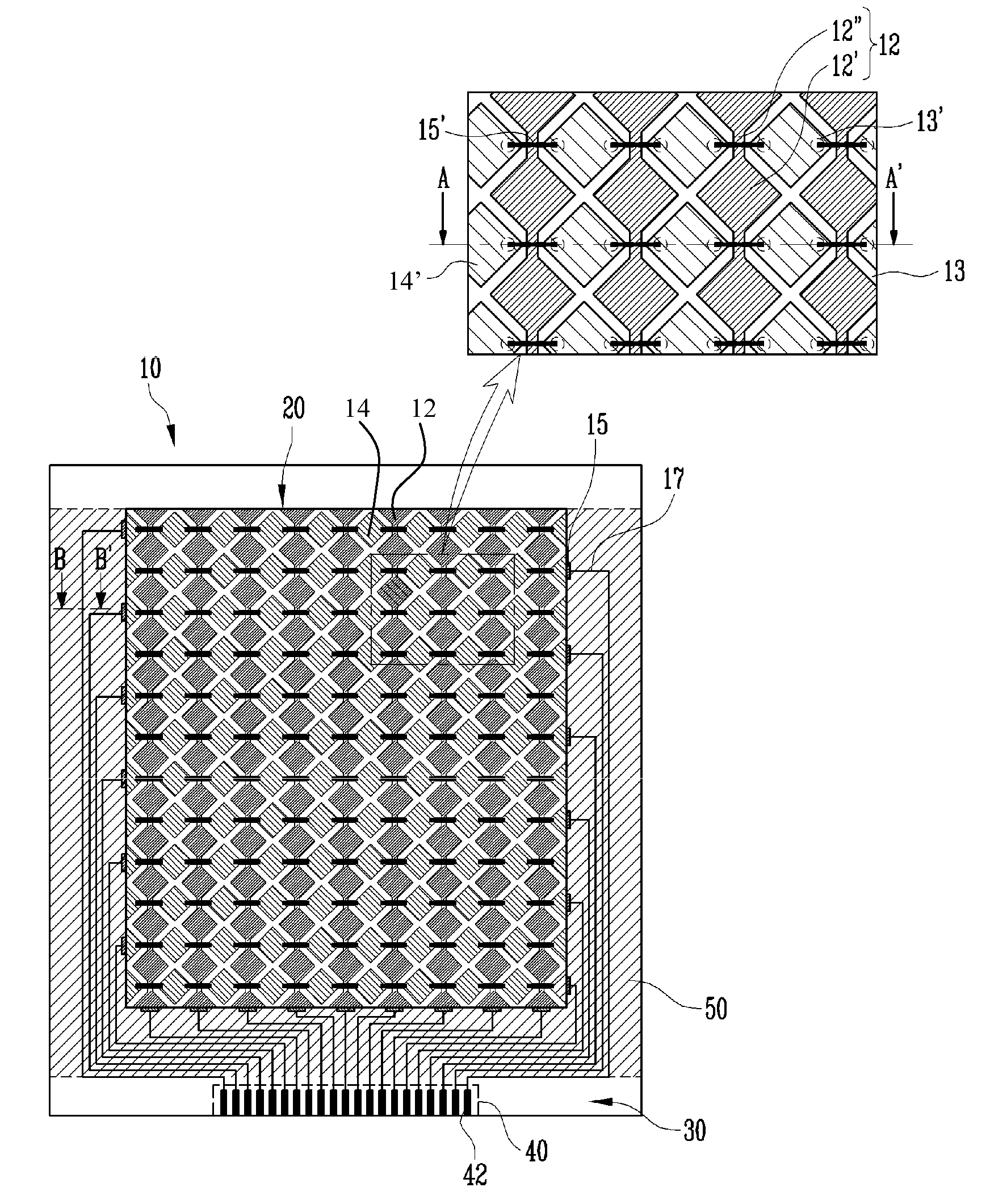
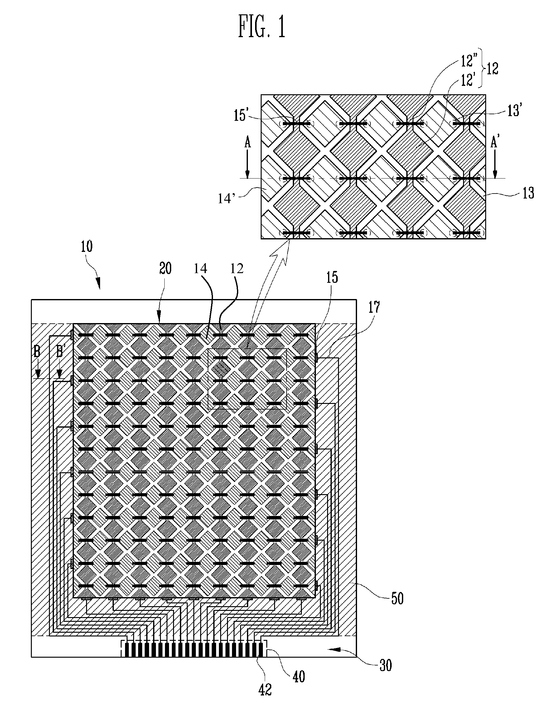
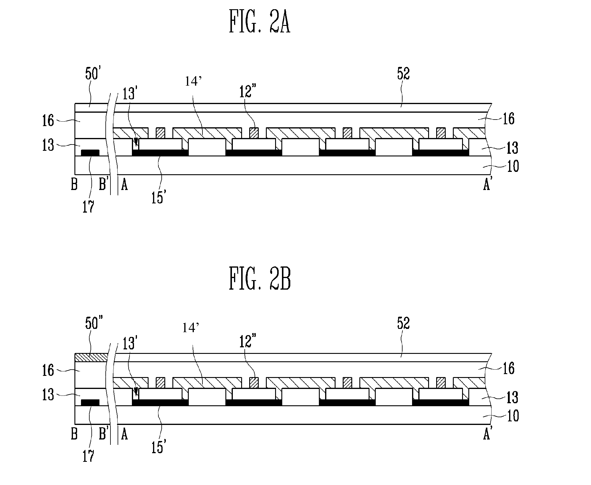
[0025]FIG. 1 is a plan view of an upper substrate 10 of a flat panel display according to an embodiment of the present invention and FIGS. 2A and 2B are cross-sectional views of specific portions (A-A′ and B-B′) of FIG. 1. Further, FIG. 3 is a plan view of a lower substrate 100 of the flat panel display corresponding to FIG. 1. Referring to FIGS. 1 through 2B, a touch screen panel according to an embodiment of the present invention is directly formed on an upper substrate 10 of a flat panel display. The flat panel display may be an organic light emitting display or a liquid crystal display. In the exemplary embodiment of the present invention, the orga...
PUM
 Abstract
Description
Claims
Application Information