
Dissolution testing with infrared temperature measurement

a technology of infrared temperature measurement and dissolution data, which is applied in the direction of heat measurement, optical radiation measurement, instruments, etc., can solve the problems of significant analytical errors, noise adversely affecting the dissolution data being acquired, and affecting the release rate of the dosage formulation being tested

Inactive Publication Date: 2011-09-08
AGILENT TECH INC
View PDF17 Cites 20 Cited by
  • Summary
  • Abstract
  • Description
  • Claims
  • Application Information

AI Technical Summary

Benefits of technology

[0014]According to another implementation, the method further includes controlling the temperatures of the

Problems solved by technology

A primary problem attending the use of temperature probes is their contribution to hydrodynamic disturbances with the vessels that can result in significant analytical errors and noise adversely affecting the dissolution data being acquired.
For example, hydrodynamic disturbances such as flow aberrations and turbulence can affect the release rate of the dosage formulation being tested.
However, the physical act of inserting the temperature probes into the media or thereafter removing the temperature probes from the media can itself cause transient hydrodynamic disturbances and eliminates the ability to monitor media temperature continuously or in real time.
Moreover, cycling temperature probes into and out from the media by manual means is laborious and time-consuming, and by automated means requires costly drive components that are subject to failure.
Moreover, temperature probes of conventional design require physical contact with the media and time to equilibrate or stabilize, and their accuracy and response time to generate measurement signals is less than optimal.

Method used


Image

  • Dissolution testing with infrared temperature measurement
  • Dissolution testing with infrared temperature measurement
  • Dissolution testing with infrared temperature measurement

Examples


Embodiment Construction

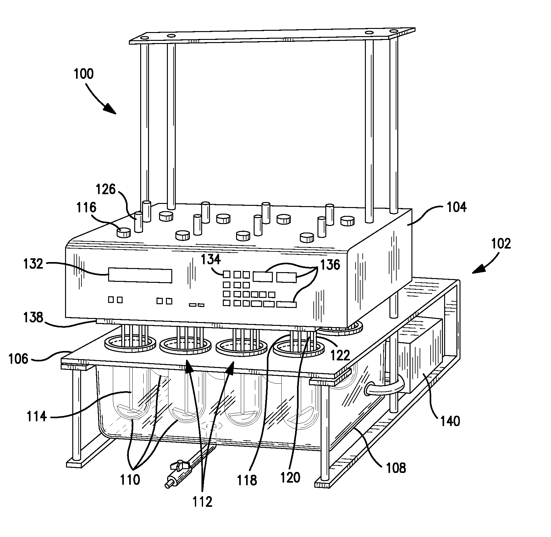
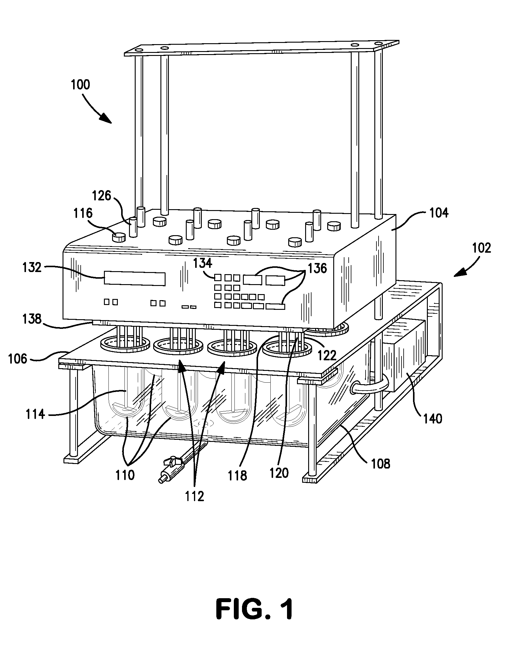
[0027]FIG. 1 is a perspective view of an example of a dissolution test apparatus 100 according to an implementation of the present disclosure. The dissolution test apparatus 100 may include a frame assembly 102 supporting various components such as a main housing, control unit or head assembly 104, a vessel support member (e.g., a plate, rack, etc.) 106 below the head assembly 104, and a water bath container 108 below the vessel support member 106. The vessel support member 106 supports a plurality of vessels 110 extending into the interior of the water bath container 108 at a plurality of vessel mounting sites 112. FIG. 1 illustrates eight vessels 110 by example, but it will be understood that more or less vessels 110 may be provided. The vessels 110 are typically locked and centered in place on the vessel support member 106 by means such as ring lock devices or clamps (not shown). Alternatively, the vessels 110 themselves may be configured to have centering capability, as disclose...


PUM


Abstract

A dissolution test apparatus may include a vessel support member, a sensor support member, infrared temperature sensors, and an electronic controller. The vessel support member may have apertures for receiving vessels. The infrared temperature sensors are mounted at the sensor support member. Each infrared temperature sensor is positioned proximate to a respective vessel mounting site to receive infrared radiation emitted by media contained in a vessel mounted at the vessel mounting site, and is configured to transmit a measurement signal indicative of the temperature of the media. The electronic controller communicates with the infrared temperature sensors and is configured to receive and process the measurement signals transmitted from the infrared temperature sensors. The electronic controller may be configured to control media temperature in the vessels.

Description

FIELD OF THE INVENTION[0001]The present invention relates generally to dissolution testing of analyte-containing media. More particularly, the invention relates to non-invasively measuring the temperature of media contained in test vessels of a dissolution test apparatus by utilizing infrared sensing techniques.BACKGROUND OF THE INVENTION[0002]Dissolution testing is often performed as part of preparing and evaluating soluble materials, particularly pharmaceutical dosage forms (e.g., tablets, capsules, and the like) consisting of a therapeutically effective amount of active drug carried by an excipient material. Typically, dosage forms are dropped into test vessels that contain dissolution media of a predetermined volume and chemical composition. For instance, the composition may have a pH factor that emulates a gastro-intestinal environment. Dissolution testing can be useful, for example, in studying the drug release characteristics of the dosage form or in evaluating the quality co...

Claims


Application Information

Patent Timeline
IPC IPC(8): G01K1/14G01J5/00
CPCG01N33/15G01N25/482
Inventor FERNANDO, C.J. ANTHONYSMIT, DEON
Owner AGILENT TECH INC
Learn More