Optical transmission system

a transmission system and optical technology, applied in the field of optical transmission systems, can solve the problems of inability to distinguish two polarized waves from each other at polarization, and achieve the effect of reducing the number of optical transmission lines and improving the quality of optical transmission lines

Inactive Publication Date: 2011-09-08
FUJITSU LTD
View PDF1 Cites 39 Cited by
  • Summary
  • Abstract
  • Description
  • Claims
  • Application Information

AI Technical Summary

Benefits of technology

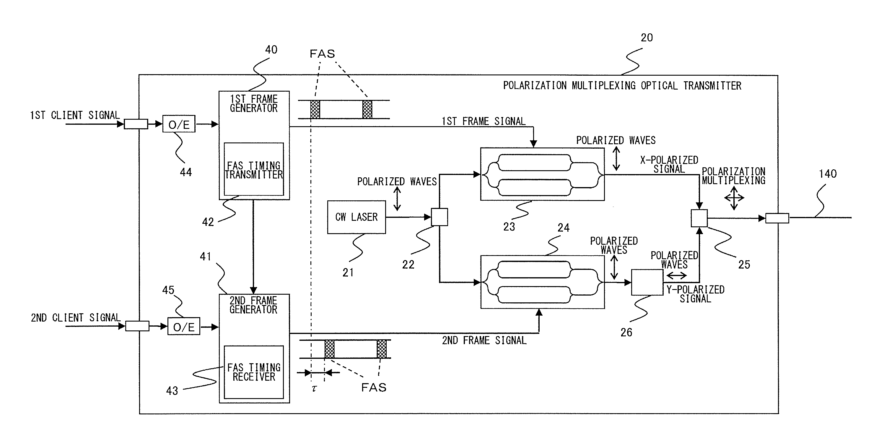
[0036]The present invention has been made in view of the foregoing circumstances, and a purpose thereof is to provide an optical transmission system that can distinguish the polarization-split signals correctly.

Problems solved by technology

However, it can create a new problem that has not been experienced before.
This problem is attributable to the two polarized waves being physically equivalent to each other and can occur whatever receiving method is employed.
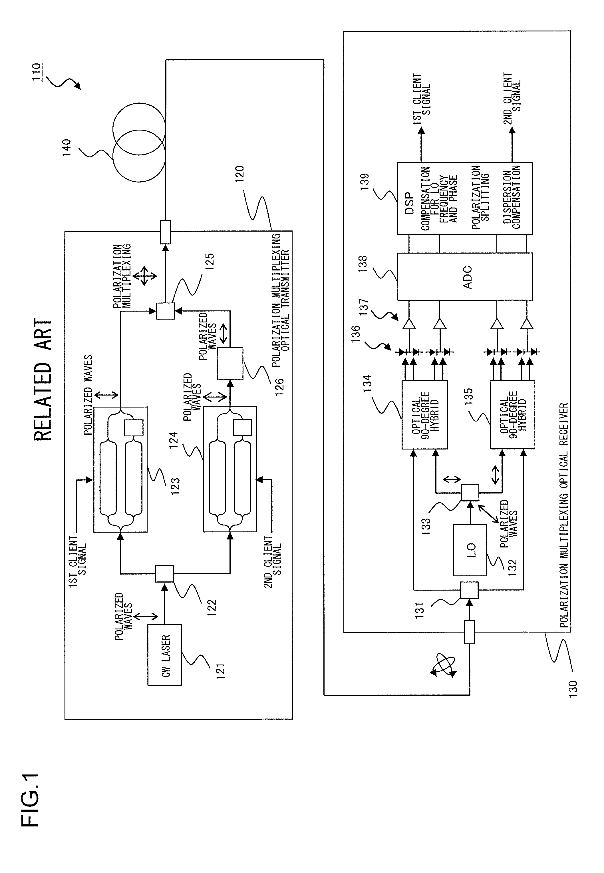
As described above, therefore, there remains a problem of inability to distinguish two polarized waves from each other at polarization splitting even when the digital coherent receiving method, which is a very useful technology, is used.

Method used


Image

  • Optical transmission system
  • Optical transmission system
  • Optical transmission system

Examples


Embodiment Construction

[0061]The invention will now be described by reference to the preferred embodiments. This does not intend to limit the scope of the present invention, but to exemplify the invention.

[0062]The best modes of carrying out the present invention will now be described in detail with reference to appended drawings. Note that in all of the Figures the same components are given the same reference numerals, respectively, and those with the identical reference numerals have their equivalent or similar structures and functions, respectively. Hence, the repeated description thereof is omitted as appropriate.

[0063]An optical transmission system according to one embodiment of the present invention comprises (i) an optical transmitter for transmitting an optical signal, where an X-polarized signal and a Y-polarized signal having predetermined frame structure are polarization-multiplexed, to an optical fiber transmission path and (ii) an optical receiver for receiving the optical signal that has pro...


PUM


Abstract

An optical transmission system includes a polarization multiplexing optical transmitter for transmitting an optical signal, where an X-polarized signal and a Y-polarized signal each having a having predetermined frame structure are polarization-multiplexed, to an optical fiber transmission path, and a polarization multiplexing receiver for receiving the optical signal that has propagated through the optical transmission path. The polarization multiplexing optical transmitter delays a frame assignment signal (FAS) in the Y-polarized signal, by a predetermined delay time τ, relative to FAS in the X-polarized signal. The polarization multiplexing optical receiver includes a polarization splitter for splitting the received optical signal into two branches of polarized signals which are orthogonal to each other, a time difference detector for detecting a time difference of FASs between the two polarized signals, and a polarization identifying unit for identifying which of the two polarized signals is the X-polarized signal or Y-polarized signal.

Description

BACKGROUND OF THE INVENTION[0001]1. Field of the Invention[0002]The present invention relates to an optical transmission system and, more particularly, to an optical transmission system employing orthogonal polarization multiplexing in which mutually independent information is put onto orthogonally polarized waves, which are then polarization-multiplexed for transmission.[0003]2. Description of the Related Art[0004]Recent years have seen the commercialization of some optical transmission systems that can transmit large-volume signals of 1 Tb / s or more, per optical fiber core, over several hundred kilometers by wavelength-multiplexing a plurality of signal channels of 40 Gb / s per wavelength. Currently, earnest efforts are being made to develop technologies capable of realizing even wider bandwidths by raising the transmission rate per wavelength to 100 Gb / s.[0005]To that end, electrical circuitry having wider bandwidth capacity must be introduced if higher transmission rates per wave...

Claims


Application Information

Patent Timeline
Patent Type & Authority Applications(United States)
IPC IPC(8): H04J14/06H04J14/08H04B10/25H04B10/532H04B10/54H04B10/556H04B10/588H04J14/00H04J14/04
CPCH04J14/08H04J14/06
Inventor MORI, SHOTA
Owner FUJITSU LTD
Why Eureka
Try Eureka