System for connecting and disconnecting containers from a base

a technology for connecting and disconnecting containers and containers, applied in the direction of loading/unloading vehicle arrangment, transportation items, load accommodation, etc., can solve the problems of human beings in potentially dangerous situations, incurring additional labor costs, and unsafe and efficient, so as to reduce the cost of purchasing and maintaining, and reduce the cost of transportation industry

Active Publication Date: 2011-09-08
WALKER PETER J
View PDF21 Cites 8 Cited by
  • Summary
  • Abstract
  • Description
  • Claims
  • Application Information

AI Technical Summary

Benefits of technology

[0036]An additional advantage of the present invention is that a single device will be used to connect containers to bases. This will decrease the purchase and maintenance costs connected to cones and chassis twist locks; again decreasing costs to the transportation industry.
[0037]Embodiments of the present invention are directed to a shipping container locking system. The shipping container locking system includes an actuating unit housed in the interior space of the upper corner fitting of a shipping container. The actuating unit includes a cup and a swivel. The cup has an interior surface and a bottom surface. The cup is capable of rotating in a generally horizontal direction about the swivel. The shipping container locking system also includes a locking mechanism. The locking mechanism is partially housed in the interior space of the lower corner fitting of a shipping container. The locking mechanism includes an internal locking leg and a collar. The internal locking leg and collar each have an orifice formed therethrough. The locking mechanism also includes a locking leg shaft having a cylindrical section protruding through the orifice of the internal locking leg and collar. The locking leg shaft is connected to a locking leg having an elongated base. The shipping container locking system also includes a vertical coupler. The vertical coupler connects the actuating unit with the locking mechanism. The shipping container locking system also includes a return means. The return means communicates elastically between the locking leg shaft and the internal locking leg. The return means has a force that is applied about the central axis of the cylindrical section of the locking leg shaft. A torsional force can be applied to the actuating unit to cause rotation of the actuating unit about the swivel. The rotation of the actuating unit pulls and imparts a tension force on the vertical coupler. The tension force on the vertical coupler causes a movement of the vertical coupler. The movement of the vertical coupler imparts a torsional force on the locking mechanism to rotate the locking leg. The torsional force on the locking mechanism causes rotation of the locking mechanism.
[0038]According to one aspect of the invention, the return means imparts a torsional force about the central axis of the cylindrical section of the locking leg shaft.
[0039]Embodiments of the present invention are directed to an apparatus to unlock a container twistlock. The apparatus includes an actuating unit housed in an interior space of the upper corner fitting of a shipping container. The interior space includes a floor, walls and a ceiling. The actuating unit includes a cup and a swivel. The cup has an interior surface and a bottom surface. The cup is able to rotate in a generally horizontal direction about the swivel. The apparatus also includes a container locking mechanism generally housed in a lower corner fitting of the container. The apparatus also includes a vertical coupler. The vertical coupler connects the actuating unit to the locking mechanism. A torsional force can be applied to the actuating unit rotating the actuating unit about the swivel. The torsional force is converted to a tension force by the actuating unit. The tension force acts on the vertical coupler to cause a movement of the vertical coupler. The movement of the vertical coupler causes the container locking mechanism to rotate and unlock.
[0040]According to one aspect of the invention, the swivel protrudes in a generally perpendicular direction to the upper corner fitting.
[0041]According to another aspect of the invention, the cup rotates about the swivel in a generally horizontal plane.

Problems solved by technology

Although these devices and systems are currently used to connect containers to various bases, they posses a number of disadvantages that make them unsafe and inefficient.
Cones require manual locking and unlocking, incurring additional labor costs and placing humans in potentially dangerous situations.
Additionally, they require personnel to work both on vessels and on the ground, again increasing labor costs.
In addition, when cones are not inserted or turned into the locking position they can become detached from a container causing additional problems, such as an unsecured connection between a container and a base or, when being hoisted by a lifting device, the cone can fall from the container, injuring or killing personnel.
Further, a cone is one form of a number of similar locking devices used to secure containers, such that additional equipment and additional purchase and maintenance costs are incurred.
Lastly, recent U.S. regulations have required that all cones used at U.S. ports be of the automatic type due to safety considerations, causing the manual cones to be unsuitable for use in the U.S.
Although automatic cones eliminate the need to manually lock containers to a base, they still require a manual release, still placing personnel into dangerous work environments.
Furthermore, automatic cones have a number of the disadvantages that manual cones posses, including: requiring personnel to work both on vessels and on the ground, the cones can fall free injuring or killing personnel below, and an automatic cone is one form of a number of similar locking devices used to secure containers such that additional equipment and therefore additional purchase and maintenance costs are incurred.
Although twist locks address some of the limitations of the previous devices, they also posses a number of disadvantages.
The manual requirement can put a person in a dangerous work environment where heavy machinery is lifting tons of equipment thereby putting an individual at risk of injury or death.
A second disadvantage of twist locks is the procedures that are adopted to prevent personnel from having to unlock containers from their bases in dangerous environments.
This method can create a number of dangerous situations in a yard.
First, the container is no longer connected to the chassis, it is merely resting on the chassis.
If an accident were to occur, the container is not connected to chassis, causing an unpredictable and potentially dangerous situation.
Additionally, while driving around a yard, the twist locks often turn accidentally into the locked position requiring the driver to exit the safety of his vehicle to reopen the twist lock, thereby defeating the goal of the procedure.
These are dangerous situations for drivers and anyone else that might be in the area.
A third disadvantage is that a twist lock is again one form of a number of similar locking devices used to secure containers such that additional equipment and therefore additional purchase and maintenance costs are incurred.
Another disadvantage of current methods of securing containers to transport modes relates to the rail industry.
This is because there is no way to access the lower corner fittings of a container that is sitting in the well of the rail car.
As a result, there is no way to manually unlock a manual or automatic cone or twist lock.
An additional disadvantage of these devises is the number of different locking devices utilized to perform a single function, connecting or disconnecting container from a base.
Another disadvantage of these devices is that they adversely effect crane cycle times by 15 to 20% during vessel loading and discharging operations.
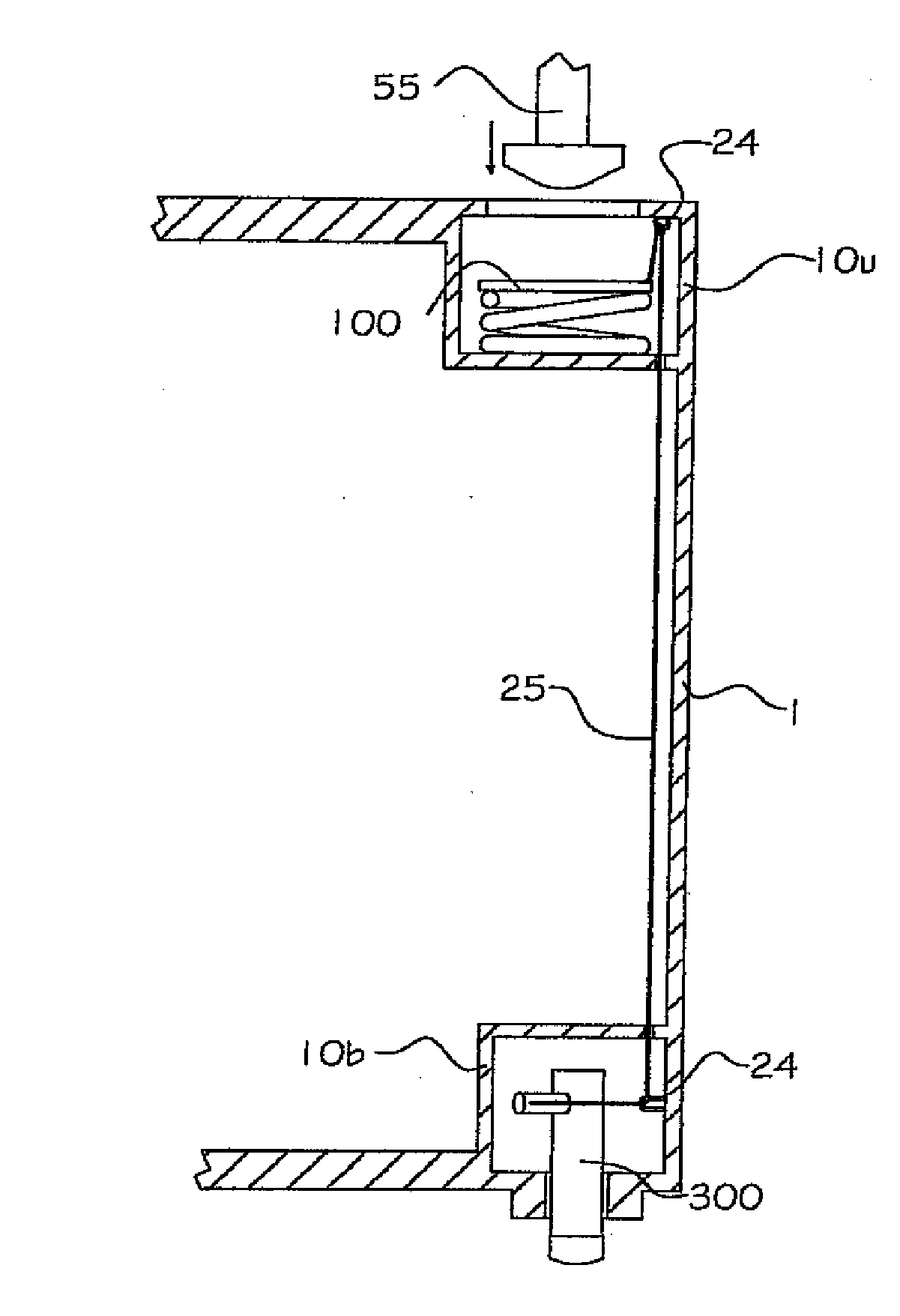
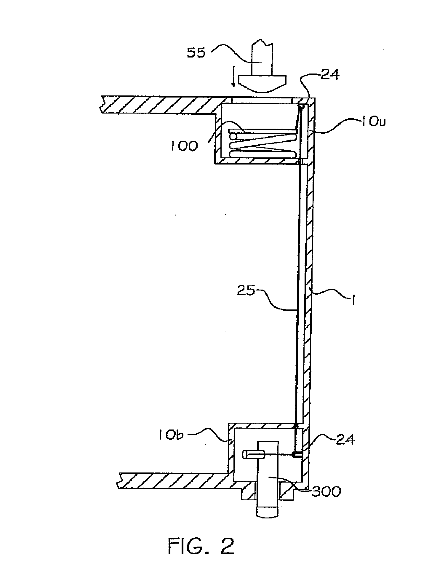
Inventions have been developed to overcome the above mentioned problems including Del Aqua's in 1982 (U.S. Pat. No. 4,341,495) and Cain's in 1976 (U.S. Pat. No. 3,980,185) These prior art forms however were not commercially viable; because the components of the inventions are intrusive into the interior space of a container, susceptible to being damaged by equipment or cargo moving into and out of containers, and would require modifications to the doors of a container.
Also, these inventions require all four upper corner castings of a container to be engaged by rotatable twist locks of a spreader which is not possible when using machines which only engage two of the upper corner castings or sites that use fork lifts to lift containers.
Lastly, the number of moving parts that comprise these are forms would be difficult and expensive to maintain in a fleet of containers spread around the world.
In another invention by Walker in 1992 (U.S. Pat. No. 7,014,234), the disadvantages of Del Aqua's and Cain's are overcome, however this prior art from has a disadvantage caused by the non-standardized depth of twist locks used to connect containers together on ships.
Additionally, equipment costs are prohibitive; cones are provided by vessels, not stevedoring companies or container yards.
The additional labor required to set, lock and unlock connecting devices is also costly.
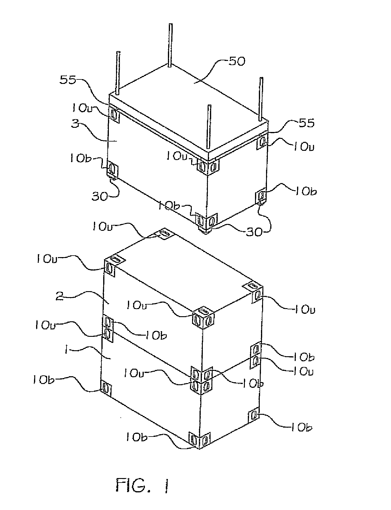
There are hazards inherent by not connecting the containers together while in a stacked configuration, such as building a disorderly pile.
While one container is being added to a stack of containers, the container being stacked may nudge another container in the stack, causing it to fall.
For obvious reasons, this is an extremely undesirable and dangerous situation, potentially causing great damage and injury.
As can be seen by existing solution attempts, the problem of providing a safe, economical, universal, and automatic means to secure containers has not been fully addressed.
Existing methods can require placing humans in dangerous situations, require many costly parts, require manual locking and unlocking, and create disorderly piles.

Method used


Image

  • System for connecting and disconnecting containers from a base
  • System for connecting and disconnecting containers from a base
  • System for connecting and disconnecting containers from a base

Examples


Embodiment Construction

[0054]The detailed description set forth below in connection with the appended drawings is intended as a description of presently-preferred embodiments of the invention and is not intended to represent the only forms in which the present invention may be constructed and / or utilized. The description sets forth the functions and the sequence of steps for constructing and operating the invention in connection with the illustrated embodiments. However, it is to be understood that the same or equivalent functions and sequences may be accomplished by different embodiments that are also intended to be encompassed within the spirit and scope of the invention.

[0055]As can be seen in FIG. 1, container 1 and container 2 are stacked, one on top of the other and a third container 3 is suspended above the stacked containers by a lifting spreader 50, in preparation to stack the third container 3. Each container has a total of eight corner fittings, four lower corner fittings 10b and four upper cor...


PUM


Abstract

A system for locking and unlocking containers to transport modes and other containers comprises an actuating unit in an upper corner fitting of a container, a mechanical connecting means connected to the actuating unit, and guides to route the connecting means from the actuating unit to a rotatable locking leg housed in a lower corner fitting of the container. The twist lock of a lifting spreader engages the upper corner fitting of a container, urging the actuating unit. The connecting means is in turn urged thereby causing the locking leg to rotate. The locking system, and apparatus to unlock a container twistlock, comprises in addition to an actuating unit, a locking mechanism in a lower corner fitting of the container, and a vertical coupler connecting the actuating unit with the locking mechanism. A torsional force applied to rotate the actuating unit is converted to a tension force by the actuating unit to move the vertical coupler, thus resulting in the rotating and unlocking of the locking mechanism.

Description

CROSS-REFERENCE TO RELATED APPLICATIONS[0001]This application is a continuation application of U.S. patent application Ser. No. 12 / 383,302, filed Mar. 23, 2009, which claims the benefit of U.S. Provisional Patent Application Ser. No. 61 / 123,535, filed Apr. 8, 2008 by the present invention. These applications are incorporated herein by reference in their entirety.FIELD OF INVENTION[0002]This invention relates generally to the locking of shipping containers. More particularly, this invention relates to a mechanism for connecting and disconnecting bulk containers to a base, such as, but not limited to, chassis, railcars, ship hatches, airline cargo decks, terminal decks and other containers.BACKGROUND[0003]When transporting or stacking bulk containers a locking device is needed to secure the containers to a base. The base could be an integral part of a transport vehicle, such as: truck chassis, railcar, aircraft, or ship hatch. Additionally, a base could be an adjacent container, when ...

Claims


Application Information

Patent Timeline
Patent Type & Authority Applications(United States)
IPC IPC(8): B60P7/13B60P1/64
CPCB65D90/0006B65D90/0026B65D90/0013
Inventor WALKER, PETER J.
Owner WALKER PETER J
Why Eureka
Try Eureka