
Pneumatic tire and method of manufacturing of the same

Inactive Publication Date: 2011-09-15
TOYO TIRE & RUBBER CO LTD
View PDF7 Cites 26 Cited by
  • Summary
  • Abstract
  • Description
  • Claims
  • Application Information

AI Technical Summary

Benefits of technology

[0007]The present invention is made by taking the actual condition mentioned above into consideration, and a purpose of the present invention is to provide a pneumatic tire which can reduce a road noise caused by a cavity resonance without deteriorating a ride comfort performance, and a method of manufacturing the same.
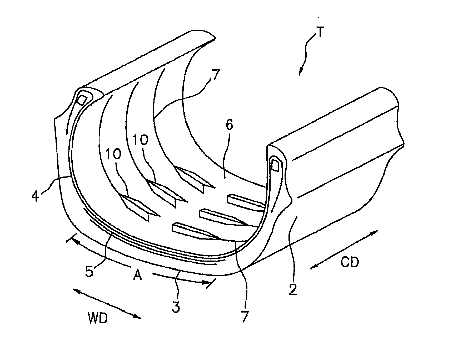
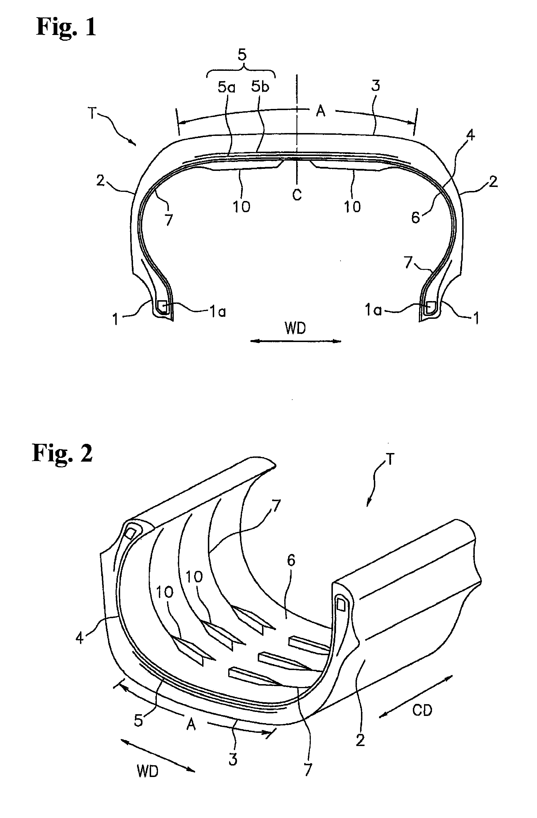
[0009]In the pneumatic tire, since a plurality of projections extending in a tire width direction while protruding out of the tire inner surface are formed so as to be spaced in the tire circumferential direction, whereby the cross sectional shape of the cavity portion of the tire is changed in the tire circumferential direction, it is possible to effectively hold down the cavity resonance noise so as to reduce the road noise. In addition, since the projection is provided in the region which is inner in the tire width direction than the end portion of the belt layer, it is possible to achieve an excellent ride comfort performance without causing an increase of a vertical rigidity of the tire.
[0011]Since the rigidity of the tread portion changes on the tire circumference, and the input from the road surface is fluctuated in correspondence thereto, by alternately providing the dense region and the coarse region of the projection as mentioned above on the tire circumference, it is possible to contribute to a reduction of the cavity resonance noise. In addition, since the coarse region is arranged at the joint position of the rubber member, it is possible to reduce a mass unbalance caused by the joint position so as to improve a uniformity of the tire.
[0012]In the pneumatic tire in accordance with the present invention, it is preferable that a distance or a phase in the tire circumferential direction of the projections is differentiated between an outer region and an inner region at a time of installing to a vehicle on the basis of a tire equator. In accordance with the structure mentioned above, it is possible to wholly hold down the cavity resonance so as to reduce the noise level, by differentiating the cycle of the vibration between the outer region and the inner region.
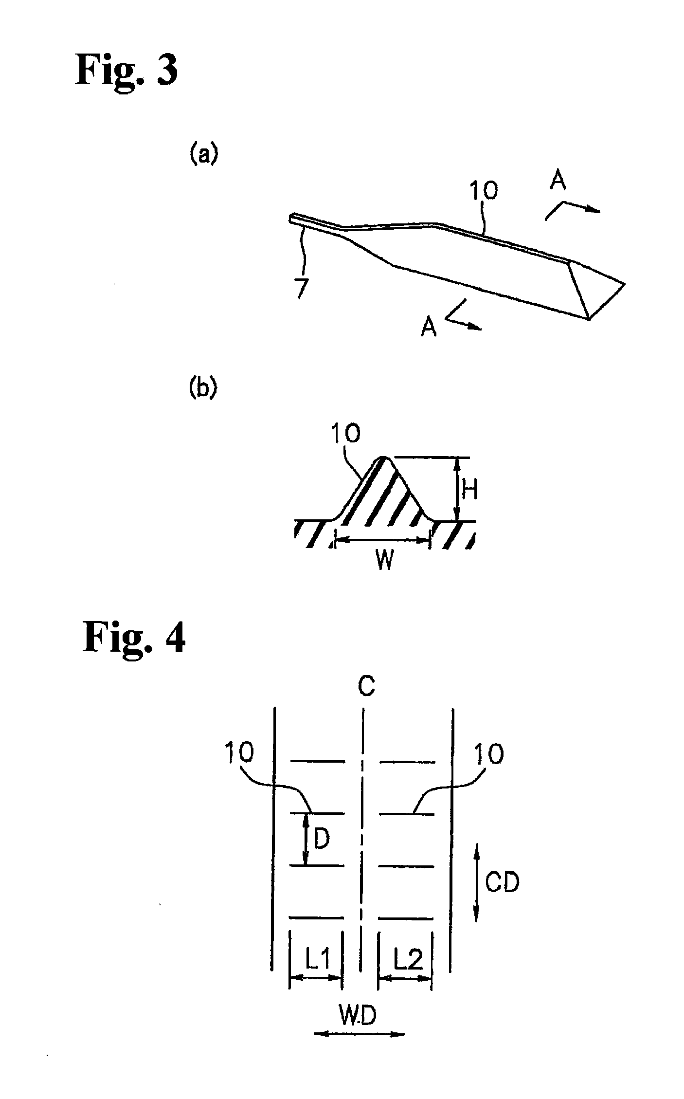
[0013]In the pneumatic tire in accordance with the present invention, it is preferable that a height of the projections from the inner surface of the tire is in a range between 2 and 8 mm. It becomes easy to secure the effect of reducing the cavity resonance noise by setting the height of the projection equal to or more than 2 mm, and it is possible to suitably prevent the rubber volume from coming short in the vicinity of the projection, by setting the height of the projection equal to or less than 8 mm.
[0014]Further, the present invention provides a method of manufacturing the any pneumatic tire mentioned above, wherein a bladder or a core in which a plurality of narrow grooves extending along the tire width direction are formed so as to be spaced in the tire circumferential direction is inserted to a green tire, the bladder or the core is pressed against an inner surface of the green tire at a time of vulcanization molding the green tire, and the projection is formed by a concave portion obtained by forming the narrow groove locally deeper and wider.

Problems solved by technology

When a vehicle travels on a rough road surface or climbs over a joint of the road surface, a noise called as a road noise may be generated in a car interior.
However, since the tread portion is bent each time when it is grounded on the road surface so as to constantly repeat a deformation, there is a risk that the material body falls off during the travel in this structure.
Further, there is such a problem that a complicated step for attaching the object to the tire is necessary.
However, if the tire inner surface is protruded in the vicinity of the tire maximum width position, an increase of a vertical rigidity of the tire is caused, therefore there is a tendency that a ride comfort performance is deteriorated.
Further, in tires described in Japanese Unexamined Patent Publications No. 2007-276712, 2007-302072 and 2006-248318, a projection is provided in a tire inner surface of a buttress portion or a side wall portion, and there is fear that the ride comfort performance is deteriorated.

Method used


Image

  • Pneumatic tire and method of manufacturing of the same
  • Pneumatic tire and method of manufacturing of the same
  • Pneumatic tire and method of manufacturing of the same

Examples


examples

[0045]An example tire which concretely shows the structure and effect of the present invention will be explained. An evaluation of each of performances is executed as follows.

[0046](1) Cavity Resonance Noise Level

[0047]A test tire was installed to an actual car (a domestically built 3.5 L mini van vehicle) so as to be traveled, a sound pressure of a noise at a time of traveling at a speed 60 km / h was measured in accordance with JASO standard, and a noise in a frequency band 250 Hz was measured. An evaluation was carried out on the basis of an index number by setting a result of a comparative example 1 as 100, it indicates that the larger the numerical value is, the smaller the cavity resonance noise level is.

[0048](2) Ride Comfort Performance

[0049]A test tire was installed to the actual car mentioned above so as to be traveled, and a point rating was carried out on a scale of one to ten in accordance with a subjective evaluation by a driver. It indicates that the larger the score is...

examples 1 to 7

[0055]As shown in FIGS. 1 and 2, tires in which a plurality of projections extending in the tire width direction are formed in the inner surface in the region coming to the inner side in the tire width direction than the end portion of the belt layer so as to be spaced in the tire circumferential direction were set to examples 1 to 7. The conditions of the shape of the projection (FIGS. 10a to 10c), with or without right and left division (FIG. 1 and FIG. 9), the arrangement in the circumferential direction (with or without the coarse and dense arrangement as shown in FIG. 5), the arrangement in the width direction (FIGS. 4, 6 and 7) are as shown in Table 1. The height and the width of the projection in each of the examples were set to the same as those of the comparative example 2, and the tire size was set to 235 / 50R18.

TABLE 1compar-compar-compar-compar-ative ative ative ative exam-exam-exam-exam-exam-exam-exam-exam-exam-exam-exam-pleplepleplepleplepleple 1ple 2ple 3ple 41234567as...


PUM

PropertyMeasurementUnit
Heightaaaaaaaaaa
Heightaaaaaaaaaa
Widthaaaaaaaaaa

Abstract

A pneumatic tire has a plurality of projections extending in a tire width direction while protruding out of an inner surface of a tire. The projections are formed in a region coming to an inner side in a tire width direction than an end portion of a belt layer embedded in a tread portion so as to be spaced in a tire circumferential direction.

Description

BACKGROUND OF THE INVENTION[0001]1. Field of the Invention[0002]The present invention relates to a pneumatic tire which can reduce a road noise caused by a cavity resonance, and a method of manufacturing the same.[0003]2. Description of the Related Art[0004]When a vehicle travels on a rough road surface or climbs over a joint of the road surface, a noise called as a road noise may be generated in a car interior. This road noise is one of the noises involved in a tire, and when the tire is excited by an input of a concavity and convexity of the road surface to the tire, the vibration is transmitted to a vehicle body through an axle or a suspension, and the noise is generated in the car interior finally. It has been known that the cavity resonance of a tire is concerned in the noise which is generated in the vicinity of 250 Hz in the car interior noise.[0005]In order to reduce the road noise caused by the cavity resonance mentioned above, Japanese Unexamined Patent Publication No. 200...

Claims


Application Information

Patent Timeline
IPC IPC(8): B60C9/02B29D30/08
CPCB29D30/0654B29D2030/0655Y10T152/10855B60C11/00B60C19/002
Inventor NAGAI, KUNIHIKO
Owner TOYO TIRE & RUBBER CO LTD
Learn More