
Linear guide apparatus

a guide apparatus and line-shaped technology, applied in the direction of bearings, bearing shafts, bearings, etc., can solve the problems of large amount large amount of work hours, and peeling of the end portions of the rolling path of the rolling element, so as to suppress the reduction in load-carrying capacity and rigidity, enhance the durability of the element, and reduce the effect of labor hours spent inspecting

Active Publication Date: 2008-05-29
NSK LTD
View PDF6 Cites 1 Cited by
  • Summary
  • Abstract
  • Description
  • Claims
  • Application Information

AI Technical Summary

Benefits of technology

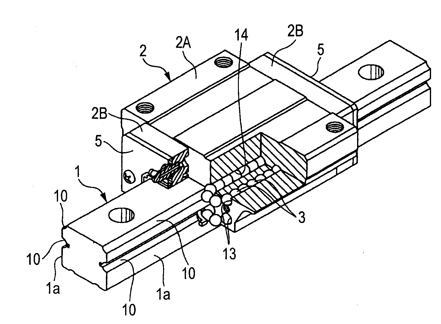
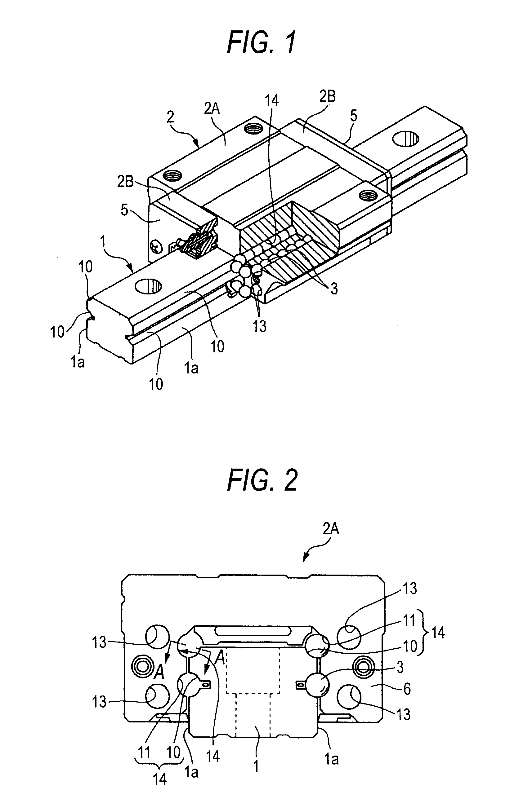
[0020]Then, the invention has been made in view of the unsolved problems inherent in the conventional examples, and an object thereof is to provide a linear guide apparatus which can enhance the durability thereof when it is driven at high speeds without deteriorating the productivity and can suppress the reduction in load-carrying capacity and rigidity without deteriorating rolling element passing vibrations.
[0052]According to the linear guide apparatus of the invention, the linear guide apparatus can be provided which can enhance the durability thereof when it is driven at high speeds without deteriorating the productivity and can suppress the reduction in load-carrying capacity and rigidity without deteriorating rolling element passing vibrations.

Problems solved by technology

However, in the above five Japanese Patent Unexamined Publications and PCT publication, which have been described above, have the following inherent problems
Even though the maximum depth of the crowing is 20 μm, the difference in level is generated between the rolling surface of the rolling element rolling path and the guide surface of the direction turning path, and when the linear guide apparatus is driven at high speeds, the rolling elements are brought into collision with the stepped portions, causing a fear that damage such as peeling is caused to occur at the end portions of the rolling element rolling path in an early stage of the life of the linear guide apparatus.
However, since this round-shaped chamfer has to have a radius of curvature of 0.1 mm or greater and be formed into a mirror surface configuration, ultra-precision grinding work is required, causing a problem with working costs.
Therefore, a tremendous amount of labor hours need to be spent inspecting to confirm that a boundary portion between the crowning and the round-shaped chamfer is formed into a shape made up of a curved surface and having no angled portion and has a radius of curvature of 0.1 mm or greater.
However, adopting this configuration decreases an area where the inner circumferential guide member which makes up the inner circumferential guide surface of the direction turning path and the end face of the slider main body, whereby a recess portion is formed between the inner circumferential surface of the inner circumferential guide member and the chamfer, and depending on the posture of the mounted linear guide apparatus, there is caused a fear that the rolling elements fall in the recess portion to thereby interrupt a smooth rolling operation thereof.
Moreover, in the JP-A-2002-155936, since the stepped portion is formed in such a manner that the edge portion of the loaded rolling surface becomes lower than the inside diameter-side side wall surface of the direction turning path, when the rolling elements roll into the direction turning path from the rolling element rolling path, the stepped portion interrupts the circulation of the rolling elements, causing a fear that the rolling elements are prevented from smooth rolling operation.
Because of this, the molding accuracy of components and machining accuracy of the slider main body need to be enhanced, and this increases the number of steps including inspections, causing a problem that the productivity is deteriorated.

Method used


Image

  • Linear guide apparatus
  • Linear guide apparatus
  • Linear guide apparatus

Examples


first embodiment

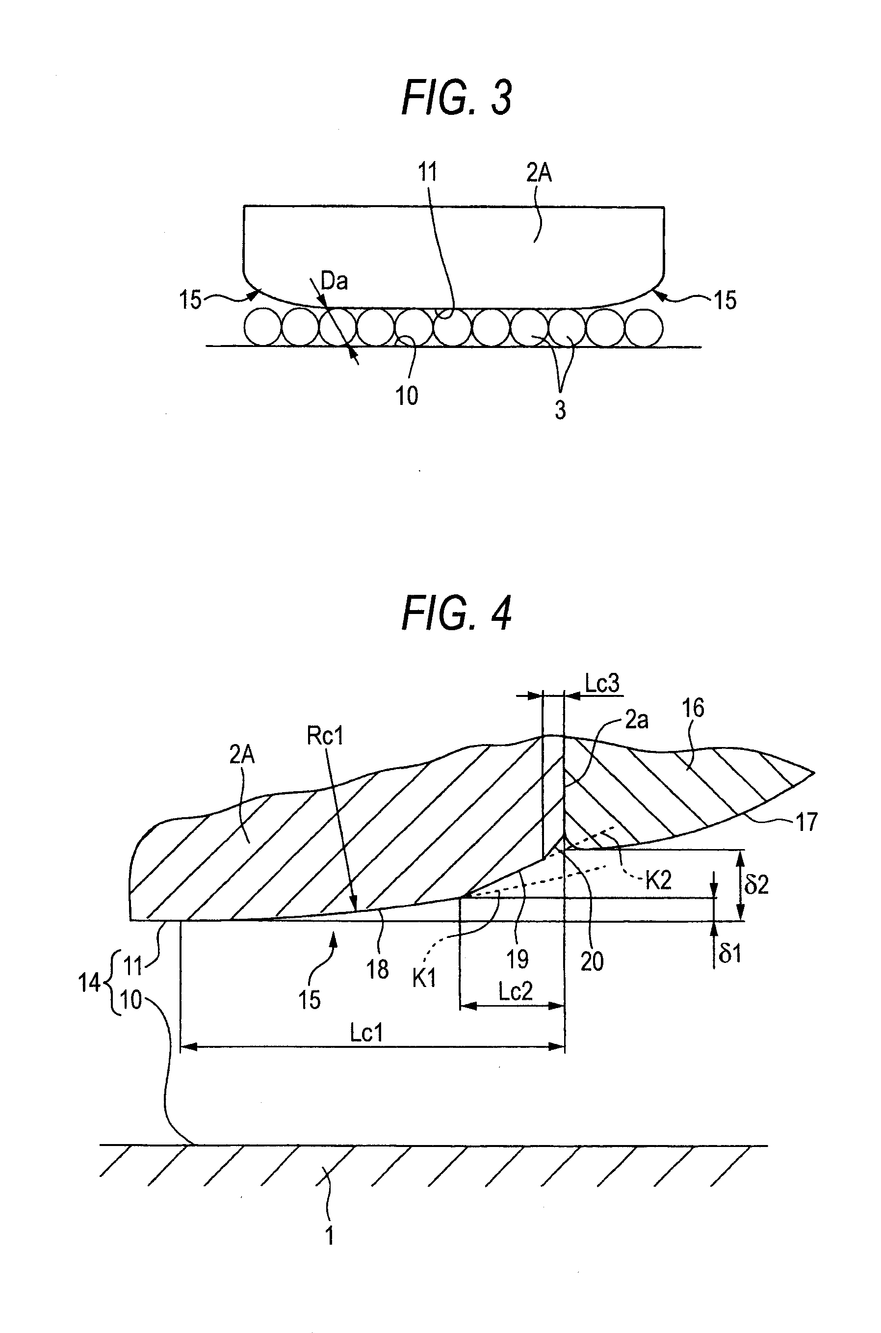
[0068]FIGS. 4 and 5 show an inclined portion 15 of a first embodiment according to the invention in an enlarged fashion. Although the inclined portion 15 is actually an extremely minute portion and has dimensions which make it difficult for the inclined portion 15 to be visible to the naked eyes, the inclined portion 15 is shown in an exaggerated fashion for the sake of understandable explanation.

[0069]In these figures, reference numeral 16 denotes a return guide (the inner circumferential guide member) interposed between the slider main body 2A and the end cap 2B, and an inner circumferential side circulation groove 17, which extends into a semi-circular arc-like shape, is formed on an outer circumference of the return guide 16. This inner circumferential side circulation groove 17 and an outer circumferential side circulation groove (not shown), which is formed on the end cap 2B so as to face the inner circumferential side circulation groove 17, make up the direction turning path ...

second embodiment

[0084]Next, FIG. 6 shows an inclined portion IS of a second embodiment according to the invention in an enlarged fashion. Note that like reference numerals are given to like configurations to those of the first embodiment shown in FIGS. 1 to 5, so as to omit the repetition of similar descriptions

[0085]In this embodiment, a round-shaped slope 22 is formed between a second crowning 19 and an end face 2a of a slider main body 2A.

[0086]Here, the rounded slope in the claim corresponds to the rounded-shaped slope 22.

[0087]In the event that the slope 20 is formed into the straight-line shape as in the first embodiment, due to a mounting error in mounting a return guide 16 relative to the end face 2a of the slider main body 2A, an end portion of the slope 20 on the second crowning 19 side protrudes towards a rolling element raceway groove 10 side, compared to an inner circumferential surface of a direction turning path (an inner circumferential side circulation groove 17 of the return guide...

third embodiment

[0089]Furthermore, FIG. 7 shows an inclined portion 15 of a third embodiment according to the invention in an enlarged fashion.

[0090]In this embodiment, a rounded portion 23 (a boundary portion between the first crowning and the second crowning being formed so as to be rounded) is formed between a first crowning 18 and a second crowning 19, and a rounded portion 24 (a boundary portion between the second crowning and the slope being formed so as to be rounded) is also formed between the second crowning 19 and a slope 20.

[0091]According to this embodiment, by forming the rounded portion between the first crowning 18 and the second crowning 19 and the rounded portion 24 between the second crowning 19 and the slope 20, since a location can be eliminated where rolling elements 3 which pass through the inclined portion 15 are brought into collision to produce a stress concentration, the component accuracy and mounting accuracy can be made stabler and the durability of the linear guide app...


PUM


Abstract

Inclined portions 15 which are provided at both end portions of a slider-side rolling element raceway groove 11 are each made up of a first crowning 18 which is formed into a curved surface shape with a large radius of curvature so as to be inclined moderately and continuously from the slider-side rolling element raceway groove, a planar second crowning 19 which neighbors the first crowning and extends towards an inner circumferential surface of a direction turning path and which is steeper in inclination than the first crowning and shorter in axial length than the first crowning, and a slope 20 which is provided between the second crowning and an end face of a slider main body and is formed steeper than the first and second crownings.

Description

BACKGROUND OF THE INVENTION[0001]1. Field of the Invention[0002]The present invention relates to a linear guide apparatus in which inclined portions are formed at both end portions of a slider-side rolling element raceway groove which makes up a rolling element rolling path.[0003]2. Description of Related Art[0004]A linear guide apparatus in which a guided body is guided in a straight line while infinitely circulating rolling elements such as rollers or balls is one of important mechanical elements which affect largely a kinetic accuracy of semiconductor manufacturing systems, ultra-precision machine tools and ultra-precision measuring equipment.[0005]The linear guide apparatus is an apparatus which includes a guide rail having a rail-side rolling element raceway groove provided thereon and a slider main body having a slider-side rolling element raceway groove provided thereon so as to face the rail-side rolling element raceway groove and supported on the guide rail so as to move in...

Claims


Application Information

Patent Timeline
Patent Type & Authority Applications(United States)
IPC IPC(8): F16C29/06
CPCF16C29/0604
Inventor MIZUMURA, YOSHINORIMATSUMURA, KEISUKE
Owner NSK LTD
Learn More