
Portable cooling or heating apparatus and method of using same

a technology of cooling or heating equipment and portable body, which is applied in the direction of domestic cooling equipment, lighting and heating equipment, furnaces, etc., can solve the problems of irregular surface, non-uniform temperature gradient around frozen materials, and thermal batteries, etc., to achieve better accuracy, increase the effect of temperature and temperature stability, and predictability of the expansion of the shape and dimension of the thermal battery

Inactive Publication Date: 2011-09-15
TOP CREATION ASIA
View PDF5 Cites 5 Cited by
  • Summary
  • Abstract
  • Description
  • Claims
  • Application Information

AI Technical Summary

Benefits of technology

[0013]The object of the present invention is to provide an improved method of maintaining temperature at a desired, pre-set level, for a long period of time and without the need for an external power source
[0016]In order to maintain a specified temperature range for the longest possible time, it is important to isolate a thermal battery from ambient temperature. This is accomplished by using an insulated container to house the thermal battery. The container is designed to be substantially air tight so that the ambient air temperature inside the container is close to that of the thermal battery. The substantially air tight container minimizes the effect that the ambient temperature can have on the thermal battery. In specific configurations of the present invention, the container has certain wall(s) which is removable (hereinafter referred to as “lid”) The removable lid may be composed of the same insulating material as the rest of the container, or of other thermally non-conductive material, and the goods can be maintained in a temperature range by being placed inside the container directly against the thermal battery. Alternatively, it can be composed of a thermally conductive material, in which case, any object whose temperature is to be maintained, such as temperature sensitive goods, may be placed against the thermally conductive lid of the container which lies flush to the thermal battery.
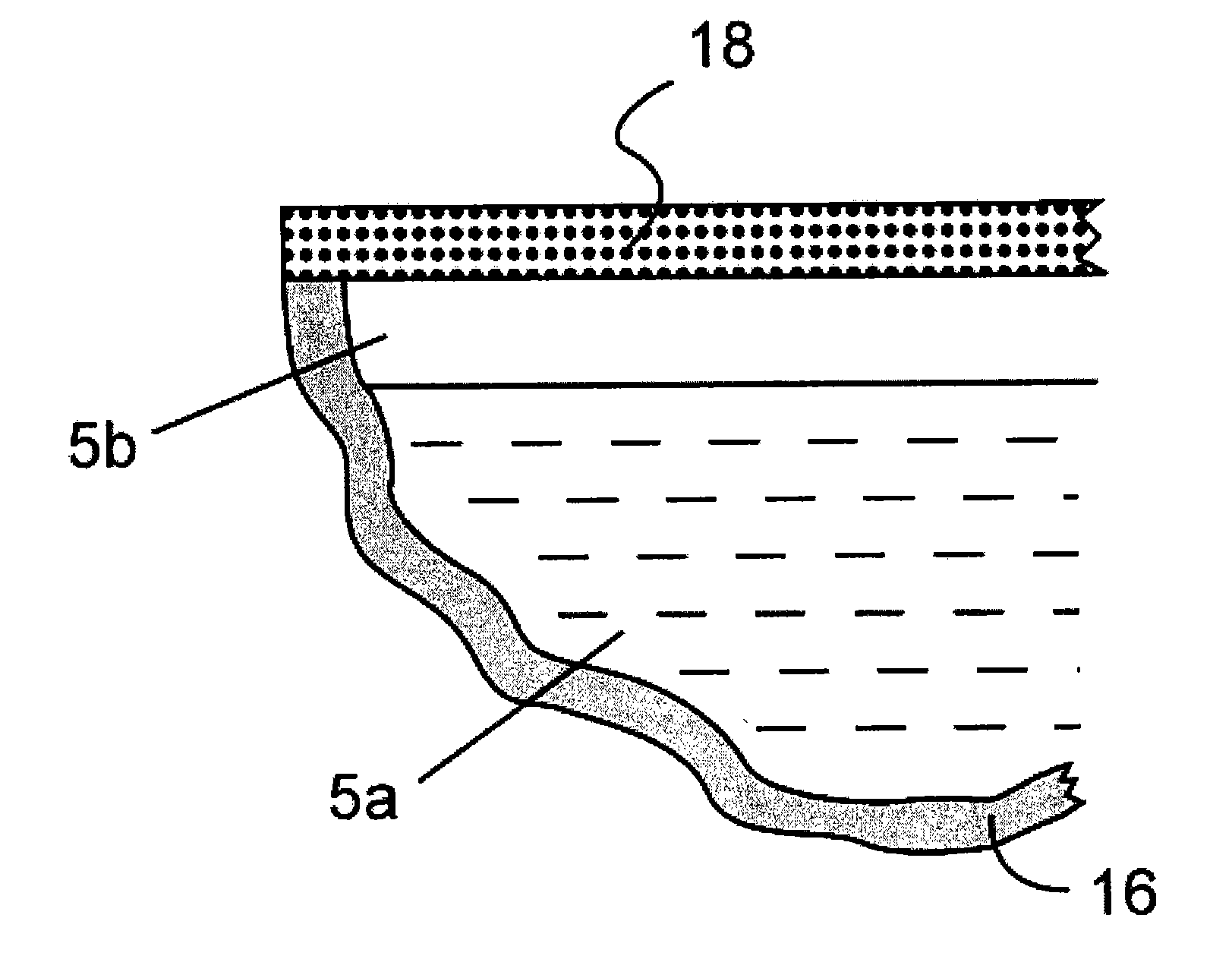
[0018]Therefore, the present invention proposes a thermal battery housing of specific construction so that at least one part of the housing surface is more rigid than the remaining surfaces. This is accomplished by using any material that exhibits a resistance to deformation under pressures likely to be encountered due to thermal expansion and retraction of the thermal battery. The remaining surface(s) would then be constructed of a material that exhibits less resistance to force than that exhibited by the rigid surface. As such, the rigid surface(s) and less rigid surface(s) work in concert to contain the thermal expansion and direct the expansion force to deform the less rigid surfaces. This enables the rigid surface(s) to maintain its original dimensions.
[0019]The present invention envisions that the thermal battery will be first processed in a freezer at a pre-set temperature to prepare it for use. During this process, expansion will take place to the thermal compound and to the thermal battery housing. As explained above, the special construction of the housing will enable certain rigid surface(s) and / or strategic areas of the housing to remain un-deformed, rendering the expanded shape and dimension of the thermal battery more predictable within a narrower range than in the prior art. The frozen and expanded thermal battery is placed inside the substantially air tight container. The container is designed so that the rigid non-deformed surface of the thermal battery is in constant contact with the goods, or the part of the container against which the goods are placed, e.g., the conductive lid. The design of the part of the container in contact with the thermal battery will vary according to the selected configuration to store or display the desired goods eg. bowl shaped for food or shaped in the form of the musical instrument to be store / displayed. The thermal battery could be secured in contact with the thermally conductive lid, or it could be in contact with another container surface eg, a vertical wall for cool storage of a vertical object As the thermal battery envisioned by the invention loses temperature and retracts to its original shape and dimensions, its rigid surface does not deform. This makes it possible to position the thermal battery so that its rigid surface remains in constant contact with the object, or desired part(s) thereof, or of such part of the container that is desired to be kept cool.
[0020]Thus the invention solves the problem of thermal batteries lacking constant contact with the container or the object to be maintained. Furthermore, the present invention allows for a manufacturer to predict, with better accuracy, the final size and shape of the thermal battery upon expansion and retraction, and to design with higher accuracy a container with higher cooling efficiency, and which will fit better the object goods it wishes to store / display

Problems solved by technology

This results in the thermal battery (which is filled with thermal compound) having an irregular surface. and non-uniform temperature gradients around the frozen material.

Method used


Image

  • Portable cooling or heating apparatus and method of using same
  • Portable cooling or heating apparatus and method of using same
  • Portable cooling or heating apparatus and method of using same

Examples


Embodiment Construction

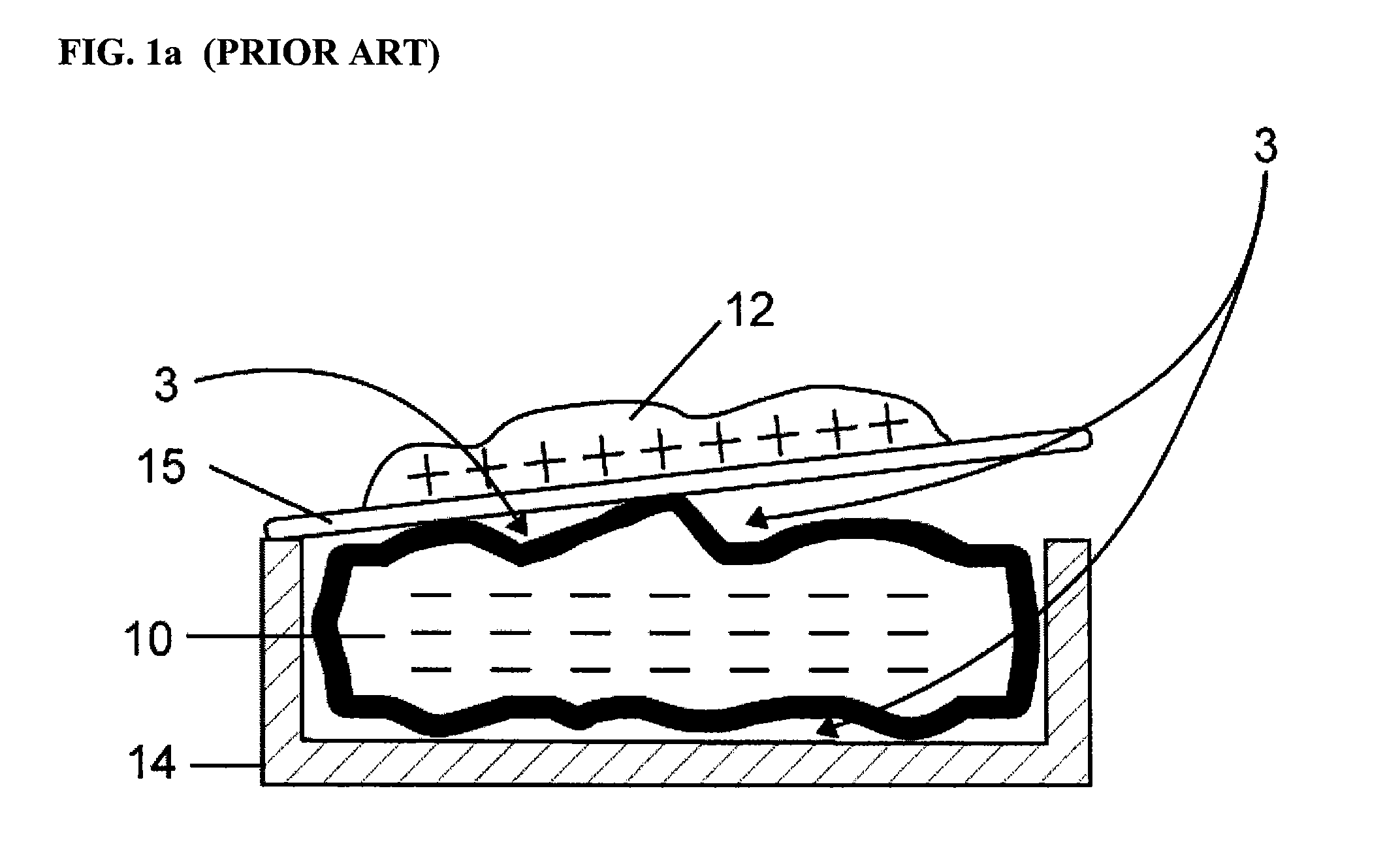
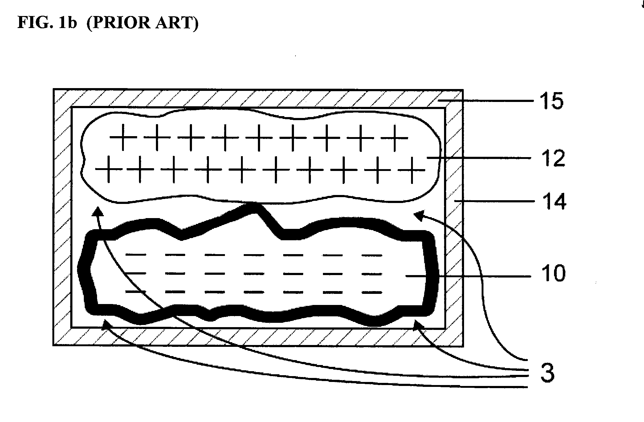
[0025]Referring now to the drawings wherein like reference numerals designate corresponding parts throughout the several views. FIG. 1a illustrates the current state of the prior art as it relates to cooling trays. FIG. 1b illustrates the current state of the prior art as it relates to cooler boxes. FIGS. 2a-d illustrate various examples for the construction of the thermal bettery as envisioned by the invention and 3a-c illustrate improved methods and apparatus for maintaining an object at a given temperature range while maintaining portability according to two embodiments of the present invention.

[0026]Specifically, as shown in FIG. 1, a thermal battery 10 as known in the prior art is depicted. This battery 10 is irregular in shape because it had undergone a freezing stage, and expanded in an unpredictable manner. It is located within a container 14 with a lid 15. It is contemplated that goods to be cooled will be placed on top of lid 15. Therefore, it is important that the thermal...


PUM

PropertyMeasurementUnit
flexibleaaaaaaaaaa
thermally conductiveaaaaaaaaaa
temperatureaaaaaaaaaa

Abstract

A portable heating and cooling apparatus and method of using the same wherein a temperature-set material is secured in a housing with both rigid and expandable sides. The housing is placed within a container which is so configured such that there is little or no disruption of the contact between the rigid surface and an object to be heated or cooled, whether such contact is direct or via some thermal conductive material.

Description

CROSS-REFERENCE TO RELATED APPLICATIONS[0001]Not applicable.STATEMENT REGARDING FEDERALLY SPONSORED RESEARCH OR DEVELOPMENT[0002]Not applicable.REFERENCE TO A COMPACT DISK APPENDIX[0003]Not applicable.BACKGROUND OF THE INVENTION[0004]The present invention relates to an apparatus and method for regulating the temperature of an object without the use of an external power supply.[0005]Currently there are many materials that need to be transported that are sensitive to temperature variations. Common examples are food products, medical and chemical samples, human organs needed for transplant, as well as archeological and forensic samples. The common methods for preserving the constant temperature of transportable materials use active mechanical refrigeration, blocks of ice, thermal gels and packs, infrared reflective thermal materials and vacuum insulated flasks and other containers.[0006]Each of these means of maintaining temperature has its own unique drawbacks. Mechanical refrigeratio...

Claims


Application Information

Patent Timeline
Patent Type & Authority Applications(United States)
IPC IPC(8): H05B3/02
CPCF25D3/08F25D2331/804F25D2303/0844F25D2303/08222
Inventor MAK, GREGORYPER JOHAN MAURITS, PERSSON
Owner TOP CREATION ASIA
Learn More