Sluice gate valve

a sluice gate valve and gate valve technology, applied in the field of valves, can solve the problems of common binding of the sluice gate, and achieve the effect of reducing binding and reducing valve binding

Inactive Publication Date: 2011-09-15
PENN TROY MACHINE
View PDF23 Cites 20 Cited by
  • Summary
  • Abstract
  • Description
  • Claims
  • Application Information

AI Technical Summary

Benefits of technology

[0011]The sluice gate valve includes at least one binding reduction mechanism to reduce binding during actuation of the sluice gate. In one embodiment the mechanism includes a the guide elements and the tracks, the guide elements and the tracks being arranged such that a predetermined amount of rotational motion of the gate around the stem is permitted during actuation of the valve to reduce valve binding. In another embodiment the mechanism includes a stuffing box assembly including a stuffing box, a bushing, and a collar, where a convex curved surface of the collar slides on a concave curved surface of the bushing such that a predetermined amount of pivoting of the stem up to a predetermined cone angle is allowed. In a preferred embodiment the sluice gate valve includes both mechanisms.

Problems solved by technology

Since the sluice gate actuates in a direction substantially parallel to the valve seat, binding of the sluice gate is a common problem in sluice gate valves.

Method used


Image

  • Sluice gate valve
  • Sluice gate valve
  • Sluice gate valve

Examples


first embodiment

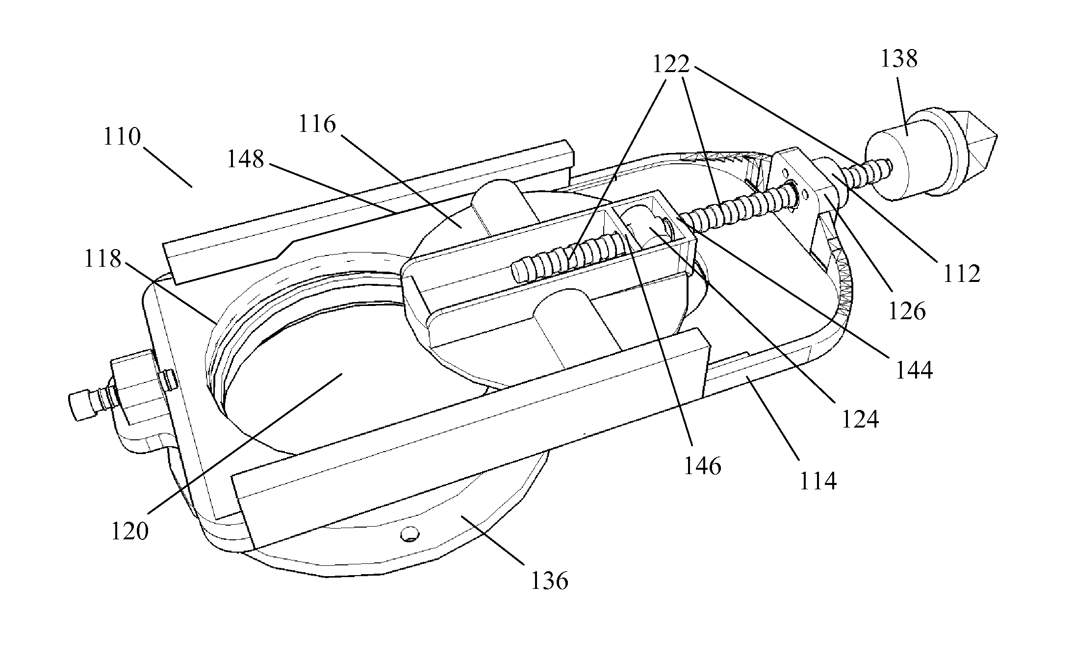
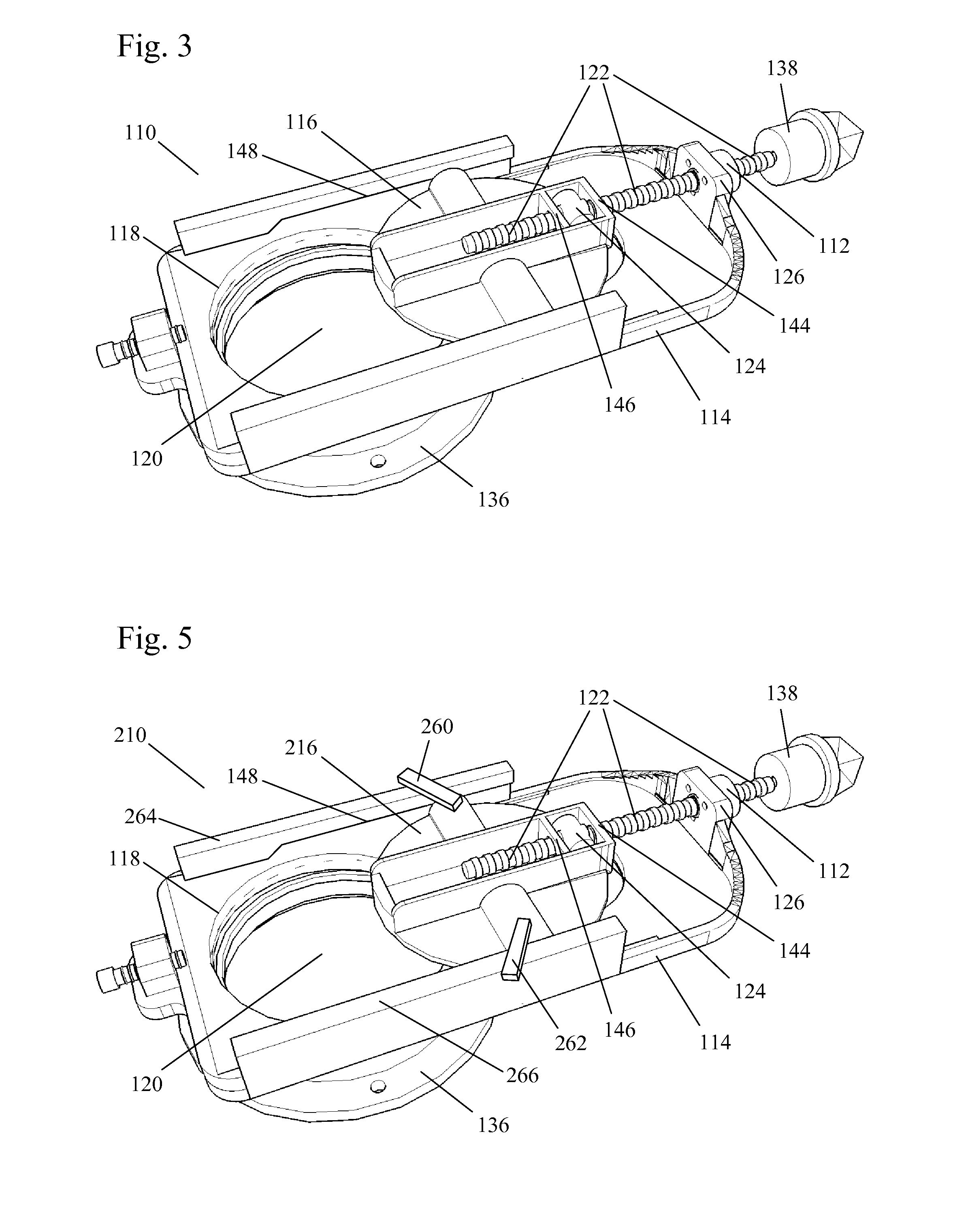
[0030]FIG. 3 and FIG. 4 show a sluice gate valve in the present invention. The sluice gate valve 110 includes a stuffing box 112, a valve body 114, and a sluice gate 116. In a closed state, the sluice gate 116 sits in the valve seat 118 to block the orifice 120 of the sluice gate valve 110. A mounting section 136 is mounted to the end of a pipe or other conduit to maintain the orifice 120 in a predetermined alignment with the conduit to be controlled by the sluice gate valve 110. The valve 110 is preferably mounted using a plurality of bolts or screws. Turning of the stem 122, which is threaded, actuates the sluice gate to open and close the valve. The sluice gate valve preferably includes a knob 138, mounted on the end of the stem 122, which is turned to actuate the valve. In the assembled state, the stem 122 passes through the stuffing box 112 and the neck 126 of the valve body. The stuffing box 112 is preferably mounted to the neck 126 by screws or bolts (not shown) through holes...

second embodiment

[0033]FIG. 5 shows a sluice gate valve in the present invention. The sluice gate valve 210 operates in a similar manner to the sluice gate valve 110 of FIG. 3 and FIG. 4, except that ears 260, 262 are attached to a front surface of the sluice gate 216. These ears 260, 262 slide along the front surfaces 264, 266 of rails on the valve body flanking the sluice gate. The front surfaces 264, 266 preferably angle rearward toward the valve seat 118 at the same angle as the tracks 148. The ears 260, 262 limit the rearward motion of the sluice gate 216 during actuation.

third embodiment

[0034]FIG. 6 through FIG. 10 show a sluice gate valve in the present invention. The sluice gate valve 310 includes a stuffing box 312, a valve body 314, and a sluice gate 316. In a closed state, the sluice gate 316 sits in the valve seat 318 to block the orifice 320 of the sluice gate valve 310. A mounting section 336 is mounted to the end of a pipe or other conduit to maintain the orifice 320 in a predetermined alignment with the conduit to be controlled by the sluice gate valve 310. The valve 310 is preferably mounted using a plurality of bolts or screws. Turning of the stem 322, which is threaded, actuates the sluice gate to open and close the valve. The sluice gate valve preferably includes a knob 338, mounted on the end of the stem 322, which is turned to actuate the valve. In the assembled state, the stem 322 passes through the stuffing box 312 and the neck 326 of the valve body. The stuffing box 312 is preferably mounted to the neck 326 by screws or bolts (not shown) through ...


PUM


Abstract

The sluice gate valve includes at least one binding reduction mechanism to reduce binding during actuation of the sluice gate. In one embodiment the mechanism includes a the guide elements and the tracks, the guide elements and the tracks being arranged such that a predetermined amount of rotational motion of the gate around the stem is permitted during actuation of the valve to reduce valve binding. In another embodiment the mechanism includes a stuffing box assembly including a stuffing box, a bushing, and a collar, where a convex curved surface of the collar slides on a concave curved surface of the bushing such that a predetermined amount of pivoting of the stem up to a predetermined cone angle is allowed. In a preferred embodiment the sluice gate valve includes both mechanisms.

Description

BACKGROUND OF THE INVENTION[0001]1. Field of the Invention[0002]The invention pertains to the field of valves. More particularly, the invention pertains to a sluice gate valve with a pivotable actuation assembly.[0003]2. Description of Related Art[0004]Sluice gate valves, also known as slide gate valves, are known in the art. The sluice gate is typically a wooden or metal plate, which may be circular or rectangular and which slides in grooves of channels in the side of the valve body to actuate the valve. Sluice gates are commonly used in rivers or canals to control water levels and flow rates, in mining operations to recover minerals, and in wastewater treatment plants.[0005]A gate valve includes an open frame and a slide. Modern sluice gates are commonly made of cast iron or stainless steel. The valve seat may be non-metallic and may have a self-adjusting design. Seats or seals of ultra high molecular weight (UHMW) polyethylene are often used to allow ease of movement and eliminat...

Claims


Application Information

Patent Timeline
Patent Type & Authority Applications(United States)
IPC IPC(8): F16K3/00
CPCF16K3/184F16K3/0218
Inventor KENNEDY, PAUL G.
Owner PENN TROY MACHINE
Why Eureka
Try Eureka