Printing process of forming two images on printing medium in overlapping manner

Active Publication Date: 2011-09-15
SEIKO EPSON CORP
View PDF12 Cites 4 Cited by
  • Summary
  • Abstract
  • Description
  • Claims
  • Application Information

AI Technical Summary

Benefits of technology

[0007]An advantage of some aspects of the invention is to implement a suitable printing process according to use or purpose while suppressing an increase in a size of the apparatus when the printing process of forming two images on a printing medium in an overlapping manner is performed.
[0012]In the printing apparatus, by forming the second image by the bi-directional image forming operations in the one direction and the opposite direction and by forming the first image by the image forming operation in the one direction, it is possible to reduce a printing time.Application Example 3

Problems solved by technology

In the printing apparatus in the related art, in addition to the image-recording head, since the supplementary recording head disposed at the upstream side and / or the downstream side in the sub scan direction is provided, there is a problem in that an apparatus for performing the printing process of forming the two images on the printing medium in an overlapping manner is increased in size.

Method used


Image

  • Printing process of forming two images on printing medium in overlapping manner
  • Printing process of forming two images on printing medium in overlapping manner
  • Printing process of forming two images on printing medium in overlapping manner

Examples


first embodiment

A. First Embodiment

A-1. Configuration of Printing System

A-2. Printing Process

A-3. Printing Mode

B. Second Embodiment

C. Modified Examples

A. FIRST EMBODIMENT

A-1. Configuration of Printing System

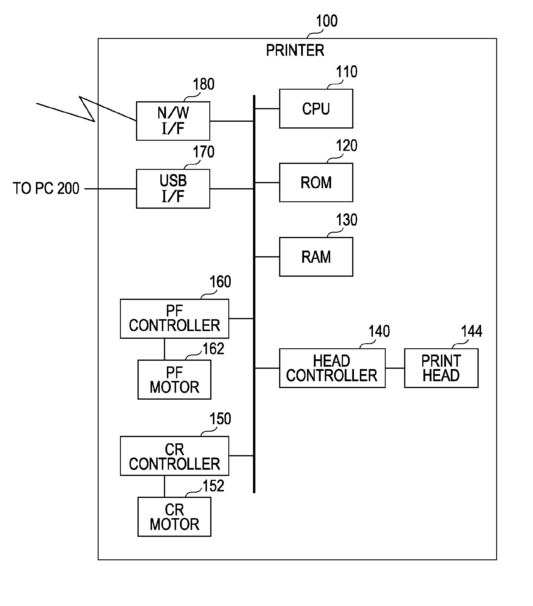
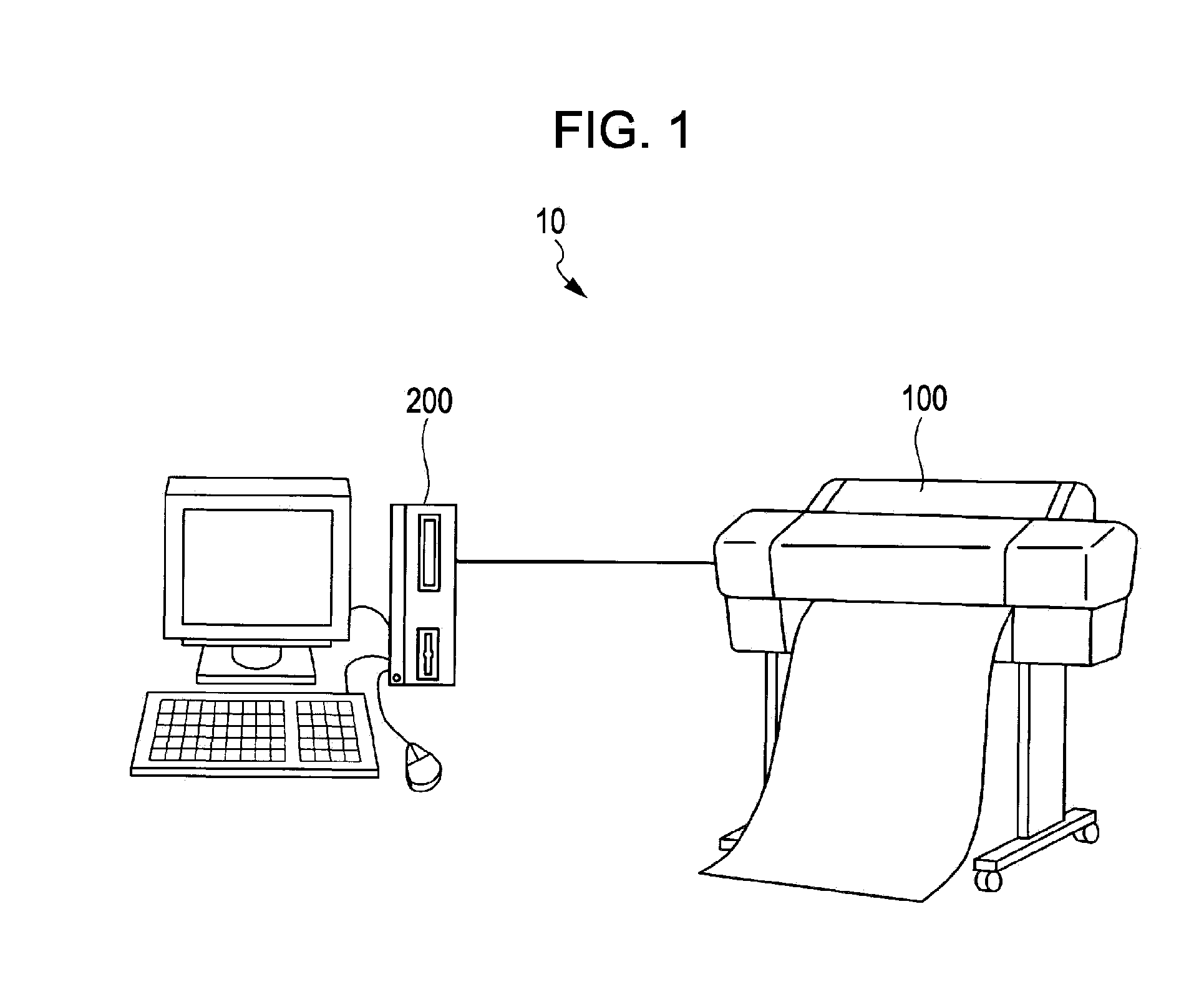
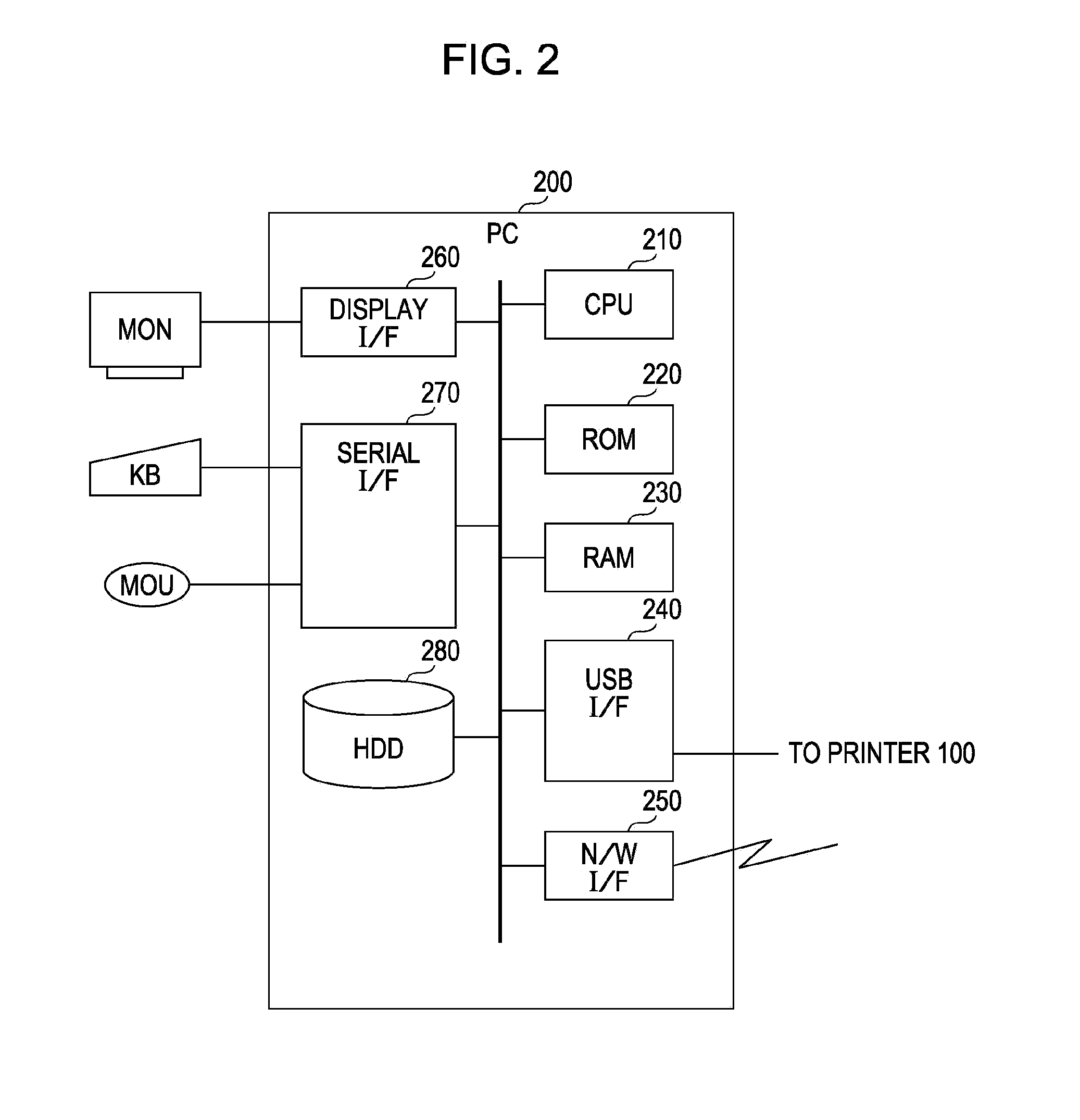
[0036]FIG. 1 is a schematic diagram illustrating a configuration of a printing system according to a first embodiment of the invention. The printing system 10 according to the embodiment includes a printer 100 and a personal computer (PC) 200. The printer 100 is an ink jet type color printer which prints an image by ejecting ink to form ink dots on a printing medium (for example, a printing paper or a transparent film). The PC 200 functions as a printing control device which supplies print data to the printer 100 and controls printing operations of the printer 100. The printer 100 and the PC 200 are connected to each other in a wired or wireless manner so that information may be able to be communicated. More specifically, in the embodiment, the printer 100 and the PC 200 are connected to each ot...

second embodiment

B. SECOND EMBODIMENT

[0077]A printing system 10 according to a second embodiment may perform a printing process of forming a color image Ic and a white image Iw to overlap on a printing medium by two printing modes, that is, a printing mode A20 in which printing image quality is preferred and a printing mode B20 in which printing speed is preferred. In addition, the configuration of the printing system 10 is the same as that of the first embodiment except for the configuration of the print head 144a. FIGS. 11 and 12 are diagrams illustrating printing methods in each printing mode of the second embodiment. In the second embodiment, each of the nozzle columns of the print head 144a is configured with 40 nozzles, and the nozzle pitch d is for one raster.

[0078]FIG. 11 illustrates a printing method in the printing mode A20 of printing image quality precedence. As illustrated in FIG. 11, in the printing mode A20, 20 nozzles (hereinafter, referred to as a “first image nozzle group in the pr...

modified example 1

C1. Modified Example 1

[0092]In the aforementioned embodiments, although the printing process of forming the color image Ic and the white image Iw in an overlapping manner by the printing system 10 is described, the invention is not limited to the printing process of forming the color image Ic and the white image Iw in an overlapping manner, but it may be generally applied to a printing process of forming two images on a printing medium in an overlapping manner.

[0093]In addition, in the aforementioned embodiments, besides the nozzle columns (nozzle columns corresponding to cyan, magenta, yellow, and black) constituting the color nozzle columns Co, the white nozzle column W may be used for forming the color image Ic, and besides the white nozzle column W, the color nozzle columns Co may be used for forming the white image Iw.


PUM


Abstract

A printing apparatus includes a controller forming an image on a printing-medium by repeating an image-forming-operation of allowing a plurality of nozzle-columns to be moved and allowing the plurality of nozzle-columns to eject ink and a transporting-operations of allowing the printing-medium to be transported. The controller forms a first-image by an image-forming-operation where the moving-direction of a nozzle-column is one direction in a second direction by using a first-image-nozzle-group configured with the nozzles included in the first-nozzle-column. In addition, the controller forms a second-image which is overlapped with the first-image by an image-forming-operation where the moving-direction of a nozzle-column is one direction and by an image-forming-operation where the moving-direction of the nozzle-column is the direction opposite to the one direction by using a second-image-nozzle-group configured with the nozzles of which positions in the first direction are different from those of the first-image-nozzle-group among the nozzles included in the second-nozzle-column.

Description

BACKGROUND[0001]1. Technical Field[0002]The present invention relates to a printing process of forming two images on a printing medium in an overlapping manner.[0003]2. Related Art[0004]There is disclosed a printing apparatus including an image-recording head which ejects image-recording ink for mainly recording an image and an supplementary recording head which is disposed at the upstream side and / or the downstream side of the image-recording head in the sub scan direction to eject a supplementary recording ink for supplementing the recording of image such as background ink or transparent ink (for example, refer to JP-A-2005-144749). The printing apparatus may be able to form two images (for example, a white background image and a color image) on a printing medium (for example, a transparent film) in an overlapping manner. JP-A-2002-307672 is an example of the related art.[0005]In the printing apparatus in the related art, in addition to the image-recording head, since the suppleme...

Claims


Application Information

Patent Timeline
IPC IPC(8): B41J29/38
CPCG06K15/105B41J2/2117
Inventor TAMAI, TAKASHITANOUE, TAKESHI
Owner SEIKO EPSON CORP
Why Eureka
Try Eureka