Liquid crystal display device, method for driving liquid crystal display device, and televesion receiver

a liquid crystal display and liquid crystal technology, applied in static indicating devices, television systems, instruments, etc., can solve the problems of increasing power consumption and pixel charging rate, and achieve the effect of suppressing horizontal-striped unevenness and reducing charging rate differences

Inactive Publication Date: 2011-09-15
SHARP KK
View PDF14 Cites 41 Cited by
  • Summary
  • Abstract
  • Description
  • Claims
  • Application Information

AI Technical Summary

Benefits of technology

[0036]As described above, according to the present liquid crystal display device, in a case where a dummy scanning period is inserted immediately after inversion of a polarity of electric potentials supplied to a data signal line, a fluctuation in load applied to a scanning signal line driving circuit during a horizontal scanning period can be made identical to a fluctuation in load applied to the scanning signal line driving circuit during a dummy scanning period. Accordingly, a status of load applied to the scanning signal line driving circuit before start of scanning, at the time of start of scanning, and during the scanning of one scanning signal line can be made identical to a status of load applied to the scanning signal line driving circuit before start of scanning, at the time of start of scanning, and during the scanning of another scanning signal line. This makes it possible to reduce a difference in charging rate between (i) pixels connected to scanning signal lines that are subjected to horizontal scanning immediately after inversion of electric potentials and (ii) the other blocks, thereby suppressing horizontal-striped unevenness which has been a problem in a case where block inversion driving is carried out.

Problems solved by technology

This results in occurrence of problems such as reduction in pixel charging rate and increase in power consumption.

Method used


Image

  • Liquid crystal display device, method for driving liquid crystal display device, and televesion receiver
  • Liquid crystal display device, method for driving liquid crystal display device, and televesion receiver
  • Liquid crystal display device, method for driving liquid crystal display device, and televesion receiver

Examples


embodiment 1

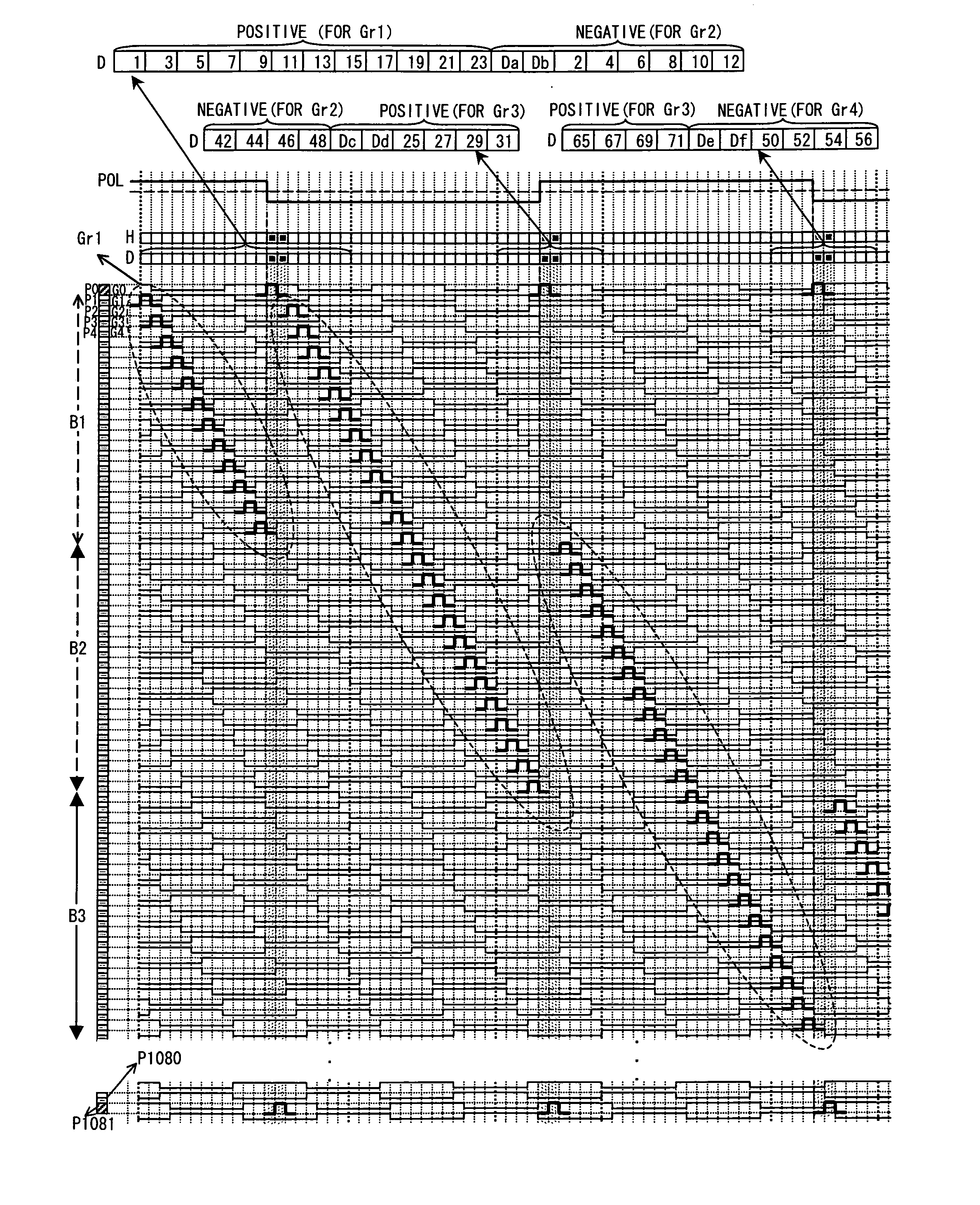
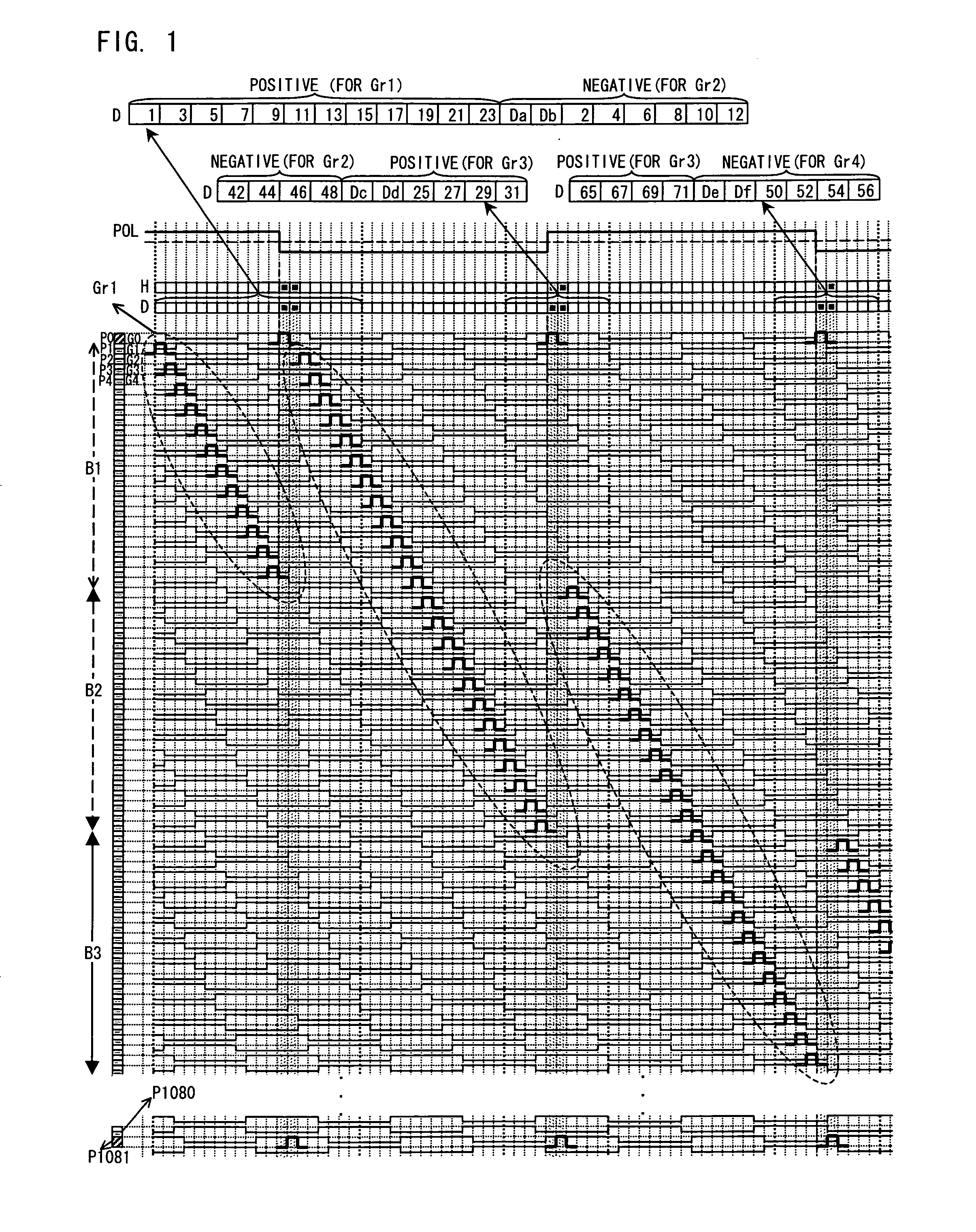
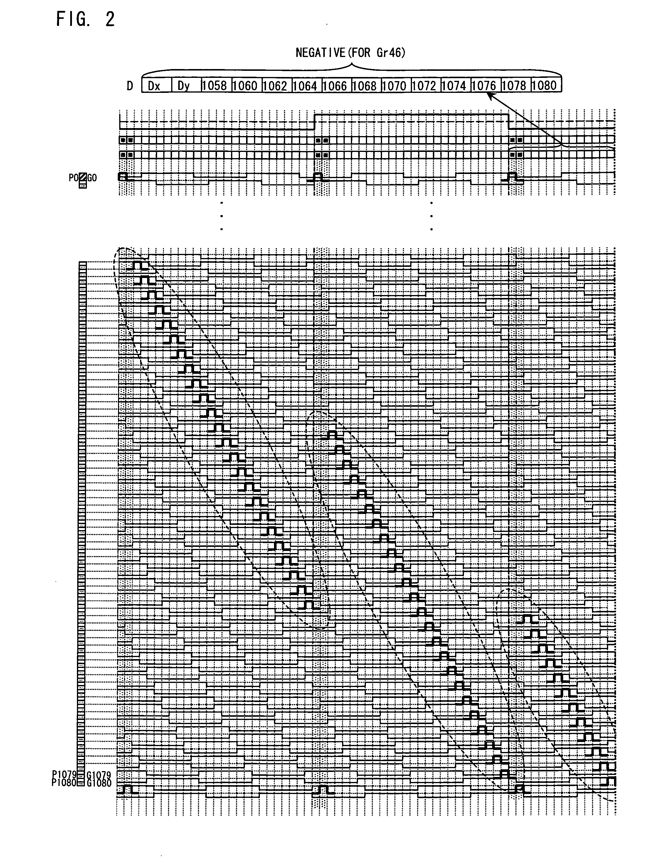
[0076]In the present embodiment, the scanning signal lines are interlace-scanned while the data signal lines are subjected to block inversion driving, as shown in FIGS. 1 and 2. First, the scanning signal line G1 and the subsequent scanning signal lines in the display area are divided into 45 blocks (B1 through B45) by 44 borders parallel to the scanning signal lines. Each of the blocks includes 24 successive scanning signal lines. For example, the block B1, which is a most upstream side block, includes the scanning signal lines G1 through G24, the block B2 includes the scanning signal lines G25 through G48, the block B3 includes the scanning signal lines G49 through G72, and the block B45, which is a most downstream side block, includes the scanning signal lines G1057 through G1080.

[0077]Then, the scanning signal lines are divided into groups as follows. Specifically, a top group Gr1 is formed which includes 12 odd-numbered scanning signal lines (G1, G3, . . . G23) included in the ...

embodiment 2

[0132]In the present embodiment, the scanning signal lines are sequentially scanned while the data signal lines are subjected to block inversion driving, as shown in FIGS. 24 and 25. First, the scanning signal line G1 and the subsequent scanning signal lines in the display area are divided into 90 blocks (B1 through B90) by 89 borders parallel to the scanning signal lines. Each of the blocks includes 12 successive scanning signal lines. For example, the block B1, which is a most upstream side block, includes the scanning signal lines G1 through G12, the block B2 includes the scanning signal lines G13 through G24, the block B3 includes the scanning signal lines G25 through G36, and the block B90, which is a most downstream side block, includes the scanning signal lines G1069 through G1080.

[0133]Then, the scanning signal lines are divided into groups as follows. Specifically, a top group Gr1 is formed which includes the 12 scanning signal lines (G1, G2, . . . G12) included in the bloc...

embodiment 3

[0167]The liquid crystal display device shown in FIG. 6 may be driven as shown in FIG. 27. Specifically, each of storage capacitor wire signals SCS0 through SCS1082 has any one of waveforms of 12 phases (first through twelfth phases represented by the storage capacitor wire signals SCS1 through SCS12, respectively).

[0168]An odd-numbered phase has a basic waveform that is repeated and that is constituted by a first section in which a Low level continues for 6H, a second section in which a High level continues for 8H, a third section in which a Low level continues for 8H, and a fourth section in which a High level continues for 6H. An even-numbered phase has a basic waveform that is repeated and that is constituted by a first section in which a High level continues for 6H, a second section in which a Low level continues for 8H, a third section in which a High level continues for 8H, and a fourth section in which a Low level continues for 6H. Note that the second phase represented by t...


PUM


Abstract

At least one embodiment of a liquid crystal display device including: scanning signal lines provided in a display area; and a dummy scanning signal line provided in a non-display area, the scanning signal lines being divided into groups each of which includes a plurality of scanning signal lines, the groups being sequentially selected, signal electric potentials of an identical polarity being sequentially supplied to a data signal line while scanning signal lines belonging to a selected group are sequentially scanned horizontally, the polarity of the signal electric potentials being inverted when the selected group is changed from a preceding group to a succeeding group which is selected immediately after the preceding group, a dummy scanning period being inserted between a horizontal scanning period corresponding to last horizontal scanning in the preceding group and a horizontal scanning period corresponding to first horizontal scanning in the succeeding group, and the dummy scanning signal line being subjected to dummy scanning during the dummy scanning period. With the arrangement, it is possible to suppress horizontal-shaped unevenness that occurs in a case where block inversion driving is carried out.

Description

TECHNICAL FIELD[0001]The present invention relates to driving (block inversion driving) in which a polarity of signal electric potentials supplied to a data signal line is inverted every plural horizontal scanning periods.BACKGROUND ART[0002]Liquid crystal display devices have excellent features such as high definition, low profile, light weight, and low power consumption. In recent years, a market scale of liquid crystal display devices has been rapidly increasing. In liquid crystal display devices, dot inversion driving in which a polarity of signal electric potentials supplied to a data signal line is inverted every 1 horizontal scanning period has been widely employed. However, in the dot inversion driving, polarity inversion frequency of the data signal line becomes high. This results in occurrence of problems such as reduction in pixel charging rate and increase in power consumption. In view of this, Patent Literature 1 for example proposes block inversion driving in which a p...

Claims


Application Information

Patent Timeline
Patent Type & Authority Applications(United States)
IPC IPC(8): H04N5/50G09G5/00
CPCG02F1/136213G09G2300/0447G09G3/3614G09G2320/0233G09G2310/0202G09G2310/08G09G2300/0413
Inventor KAWABATA, MASAESHIMOSHIKIRYOH, FUMIKAZUTSUCHIYA, TOSHIKAZU
Owner SHARP KK
Why Eureka
Try Eureka