Ultraviolet ray measuring apparatus and electronic wristwatch equipped with ultraviolet ray measuring function

Inactive Publication Date: 2011-09-15
SEIKO INSTR INC
View PDF2 Cites 57 Cited by
  • Summary
  • Abstract
  • Description
  • Claims
  • Application Information

AI Technical Summary

Benefits of technology

[0028]According to the present application, the ultraviolet ray sensor measures the ultraviolet intensity of ultraviolet rays irradiated to the ultraviolet ray receiving surface. In addition, the control unit performs control to measure ultraviolet intensity in a case in which the ultraviolet ray receiving surface

Problems solved by technology

Ultraviolet ray sensors output the maximum value when facing the sun, and therefore, if not facing the sun, the volume of ultraviolet rays cannot be measured accurately.
However, in a case in which an ultraviolet ray measuring function is provided in devices that are worn on the body, such as a pedometer, a wristwatch or the like, hanging from the neck, or in small-sized mobile ultraviolet ray measuring devices in the related art, the direction of the devices is not fixed and therefore the direction of the ultraviolet ray sensor varies with

Method used


Image

  • Ultraviolet ray measuring apparatus and electronic wristwatch equipped with ultraviolet ray measuring function
  • Ultraviolet ray measuring apparatus and electronic wristwatch equipped with ultraviolet ray measuring function
  • Ultraviolet ray measuring apparatus and electronic wristwatch equipped with ultraviolet ray measuring function

Examples


first embodiment

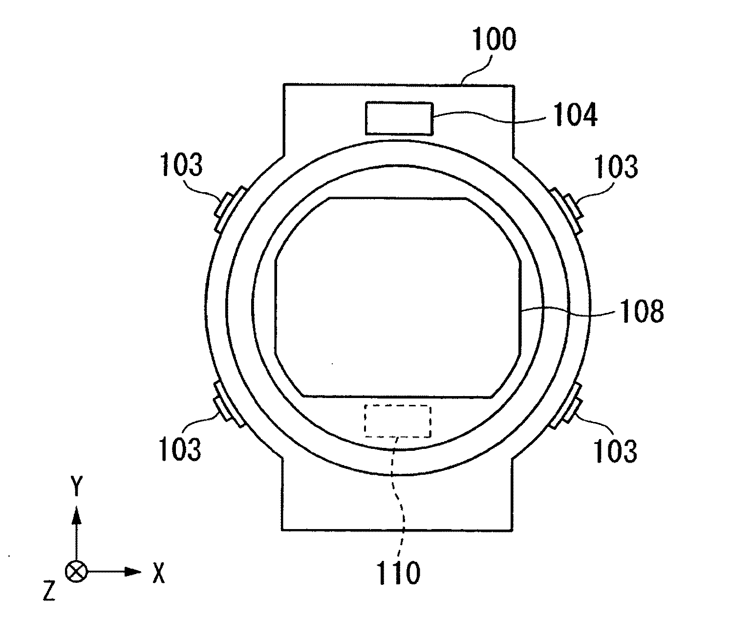
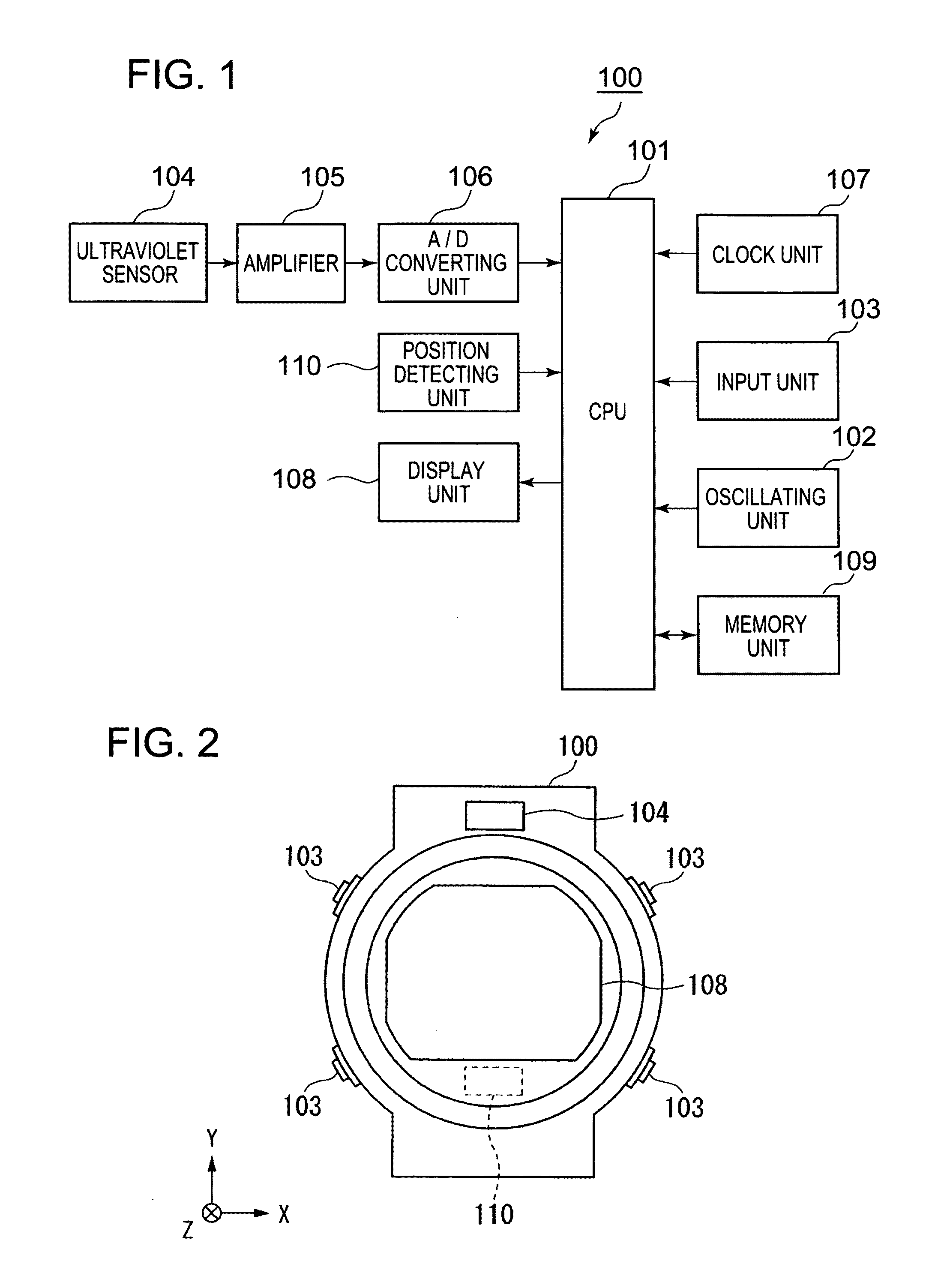
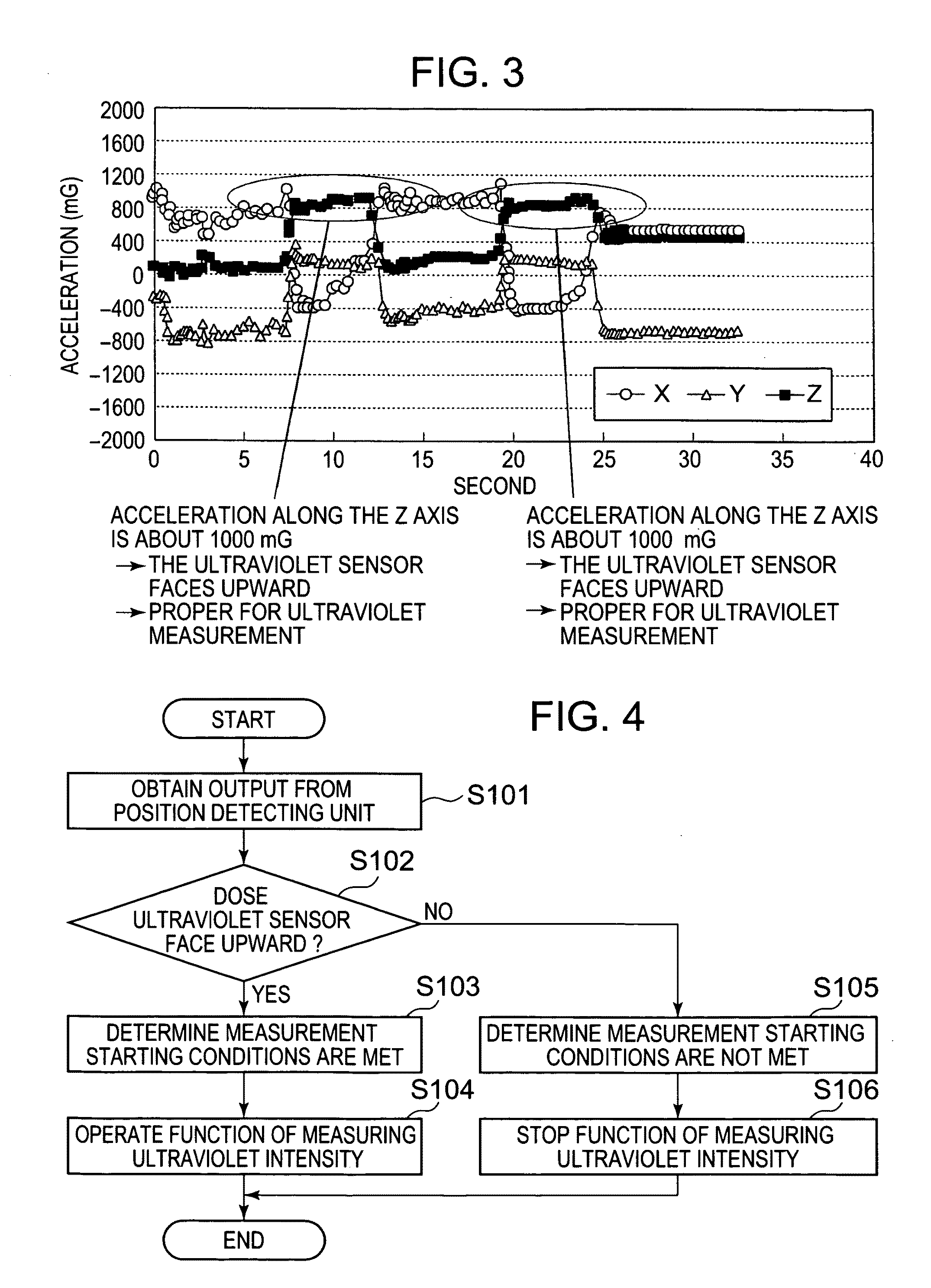
[0060]Hereinafter, the first embodiment of the invention will be described with reference to the accompanying drawings. FIG. 1 is a block diagram showing the configuration of an ultraviolet ray measuring apparatus according to the embodiment. In the example shown in the drawing, an ultraviolet ray measuring apparatus 100 includes a CPU 101 (a Central Processing Unit, a control unit), an oscillating unit 102, an input unit 103, an ultraviolet ray sensor 104, an amplifying unit 105, an analog-digital (A / D) converting unit 106, a clock unit 107, a display unit 108, a memory unit 109 and a orientation detecting unit 110.

[0061]The CPU 101 performs the control of each of the units included in the ultraviolet ray measuring apparatus 100. The oscillating unit 102 outputs reference clock signals for the CPU 101 or clock signals for timekeeping. The input unit 103 is configured with externally operable switches and receives input. The ultraviolet ray sensor 104 includes an ultraviolet ray rec...

second embodiment

[0077]Hereinafter, the second embodiment of the invention will be described with reference to the accompanying drawings. The configuration of the ultraviolet ray measuring apparatus 100 of the embodiment is identical to the configuration of the ultraviolet ray measuring apparatus 100 of the first embodiment. The difference between the ultraviolet ray measuring apparatus 100 of the embodiment and the ultraviolet ray measuring apparatus 100 of the first embodiment is that the ultraviolet ray measuring apparatus 100 of the embodiment obtains the ultraviolet intensity for a fixed period at a fixed interval (sampling) and considers the maximum value as the measured value when performing the measurement of ultraviolet intensity. This is for further reducing power consumption by obtaining the ultraviolet intensity at a fixed time interval, instead of obtaining the ultraviolet intensity at all times, when performing the measurement of ultraviolet intensity. Here, the fixed time period and f...

third embodiment

[0092]Hereinafter, the third embodiment of the invention will be described with reference to the accompanying drawings. The configuration of the ultraviolet ray measuring apparatus 100 of the embodiment is identical to the configuration of the ultraviolet ray measuring apparatus 100 of the second embodiment. The difference between the ultraviolet ray measuring apparatus 100 of the embodiment and the ultraviolet ray measuring apparatus 100 of the second embodiment is that the ultraviolet ray measuring apparatus 100 of the embodiment starts the next measurement of ultraviolet intensity only in a case in which a fixed time period has elapsed from the previous measurement of ultraviolet intensity. This is for further reducing power consumption by starting the measurement of ultraviolet intensity every fixed time period since ultraviolet intensity is not frequently changed. Here, the time interval (a fixed time period), at which the ultraviolet ray measuring apparatus 100 starts the meas...


PUM


Abstract

The ultraviolet ray sensor measures the intensity of ultraviolet rays irradiated to the ultraviolet ray receiving surface. The CPU performs control to measure ultraviolet intensity in a case in which the ultraviolet ray receiving surface of the ultraviolet ray sensor faces in a predetermined direction.

Description

BACKGROUND OF THE INVENTION[0001]1. Field of the Invention[0002]The present invention relates to an ultraviolet ray measuring apparatus and an electronic wristwatch equipped with an ultraviolet ray measuring function.[0003]2. Background Art[0004]In the past, electronic devices equipped with an ultraviolet ray measuring function were known that included an ultraviolet ray sensor and measured ultraviolet intensity and displayed measurement results (for example, refer to JP-UM-A-6-51837, JP-UM-A-2-60828, and JP-UM-A-2-16031). In addition, in electronic devices that measure the amount of ultraviolet rays, it is common that measurement is started by pressing a start switch that gives a command for the measurement of ultraviolet rays.[0005]In addition, as electronic devices equipped with an ultraviolet ray measuring function in the related art, electronic devices are known that are configured to display instantaneous values when measuring ultraviolet intensity, or cumulative values of ult...

Claims


Application Information

Patent Timeline
IPC IPC(8): G04B47/06G01J1/42
CPCG01J1/02G01J1/0219G04G21/02G01J1/429G01J1/0228
Inventor TSUBATA, KEISUKEIHASHI, TOMOHIROSAKAI, SATOSHINAKAMURA, HISAONOGUCHI, ERIKOKATO, KAZUOSUGAI, YOSHINORI
Owner SEIKO INSTR INC
Why Eureka
Try Eureka