Strain-releif member and fiber optic drop cable assembly using same

a drop cable and strainer technology, applied in the direction of optics, fibre mechanical structures, instruments, etc., can solve the problems of fiber optic cable strength components, drop cable assemblies can experience mechanical strain on the connectorized end of the assembly, and the optical transmission component and strength components are broken in the fiber optic cable,

Active Publication Date: 2011-09-15
CORNING OPTICAL COMM LLC
View PDF12 Cites 39 Cited by
  • Summary
  • Abstract
  • Description
  • Claims
  • Application Information

AI Technical Summary

Benefits of technology

[0005]An aspect of the disclosure is a fiber optic drop cable assembly. The assembly includes a fiber optic cable having a preferential bend axis and having an end portion with an end. The assembly also includes a fiber optic connector having a back end portion with an end, with the connector being operably coupled to the fiber optic cable through the connector end. The assembly further includes a strain-relief member surrounding the fiber optic cable end portion and secured to the connector end portion. The strain-relief member comprises a flexible material and is configured to limit an amount of strain in the strength components to less than 0.041 when subjected to a flex test carried out at −40° C. and +40° C. with −90° and +90° bends, at torsion angles of 0°, +45° and +90°, and with a 15 lb load.

Problems solved by technology

Such bending could lead to attenuation and even breakage of the optical transmission component and strength components in the fiber optic cable.
When deployed in the field, a drop cable assembly can experience a mechanical load that strains the connectorized end of the assembly.
The twisting action places a great deal of strain on the strength components and the optical transmission component that, if not mitigated, can damage the drop cable assembly.
Unfortunately, conventional strain-relief members used for other types of drop cables (including round cross-section drop cables) are not capable of mitigating the strain that occurs in a drop cable assembly having a preferential bend axis when the assembly is subjected to a mechanical load over a range of possible operating temperatures.

Method used


Image

  • Strain-releif member and fiber optic drop cable assembly using same
  • Strain-releif member and fiber optic drop cable assembly using same
  • Strain-releif member and fiber optic drop cable assembly using same

Examples


Embodiment Construction

[0024]Reference is now made to embodiments of the disclosure, exemplary embodiments of which are illustrated in the accompanying drawings. In the description below, like elements and components are assigned like reference numbers or symbols. Cartesian coordinates are shown in some Figures for the sake of reference, with a black circle indicating a direction into the page and a white circle indicating a direction out of the page.

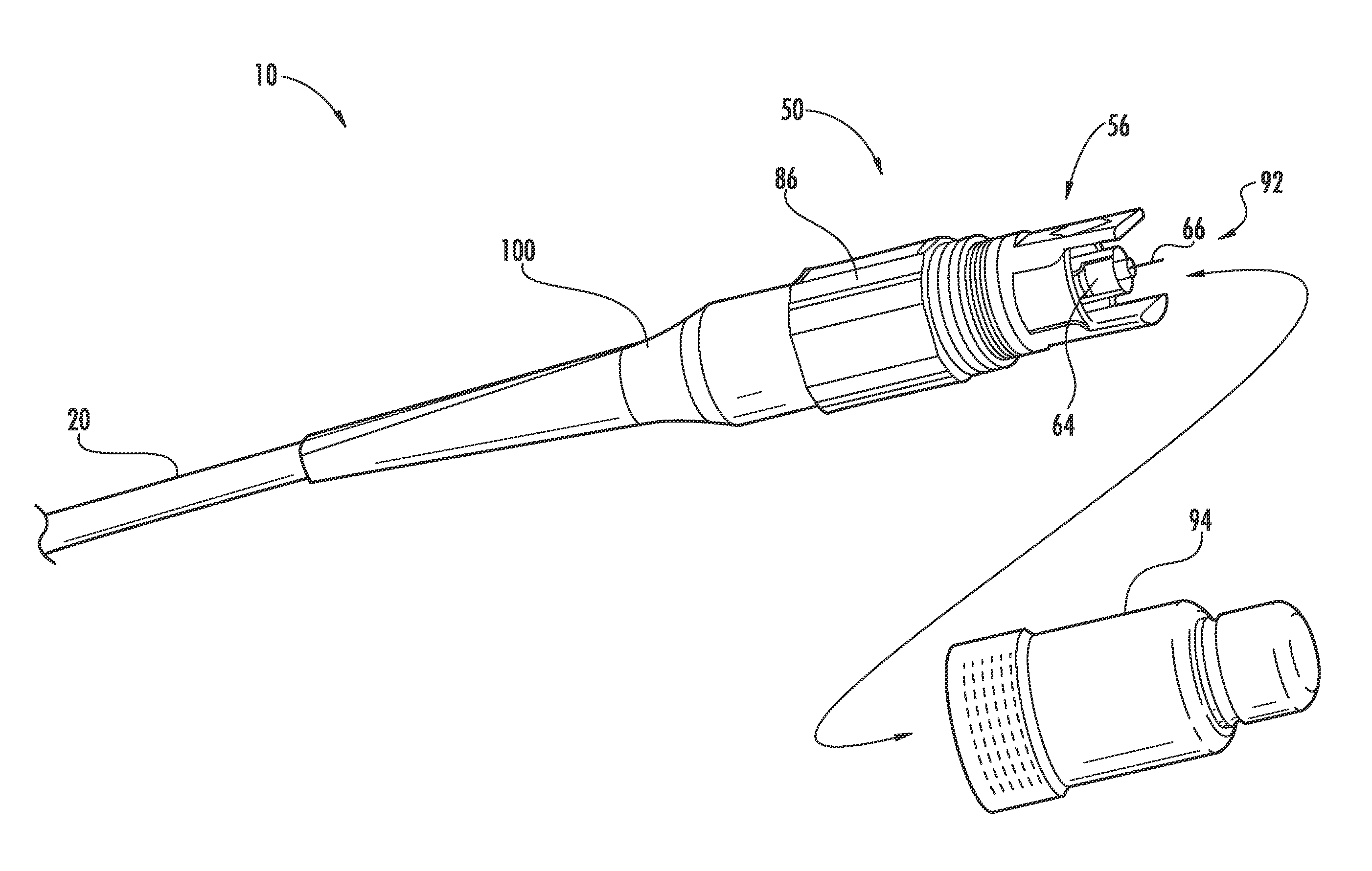
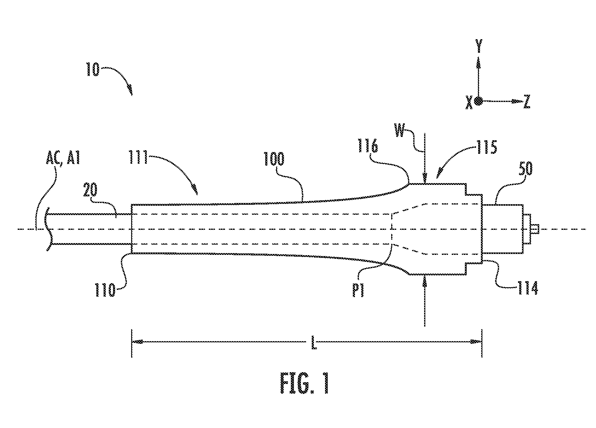
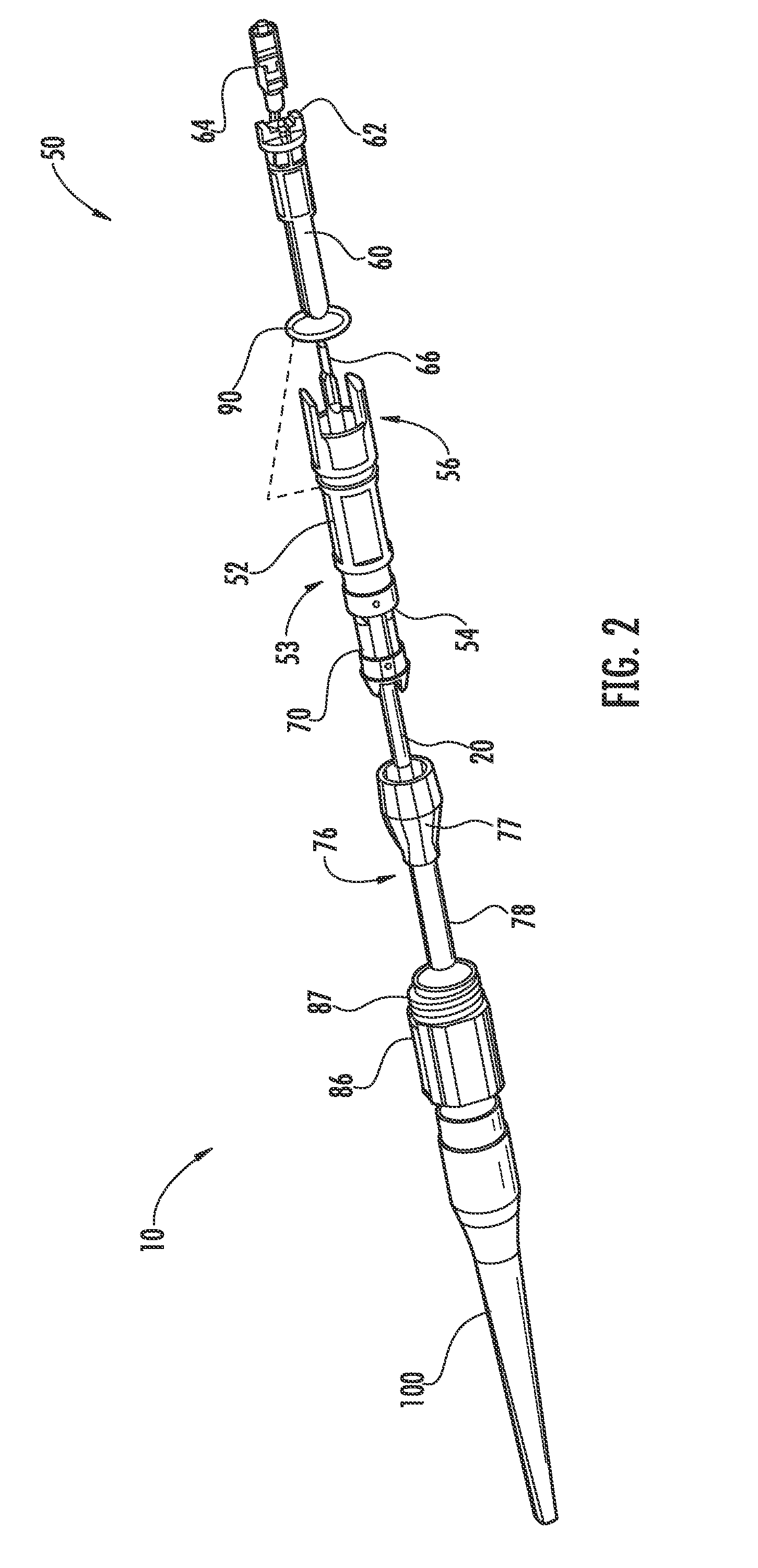
[0025]FIG. 1 is a schematic side view of a generalized fiber optic drop cable assembly (“cable assembly”) 10. Cable assembly 10 has a central axis AC and includes a fiber optic cable (“cable”) 20 having preferential and non-preferential bend axes, as discussed below. Cable assembly 10 also includes a fiber optic connector (“connector”) 50 operably connected to cable 20, and a cone-like strain-relief member 100 operably connected to the connector and the cable. Strain-relief member 100 has an axis A1, a length L as measured along axis A1, and a maximum width W...


PUM


Abstract

A strain-relief member having a body formed from a block copolymer and designed for use in a fiber optic drop cable assembly. The body has a central channel and a cylindrical connector-end portion sized to surround an end-portion of a connector. The body also has a tapered cable-end portion sized to surround an end portion of a fiber optic cable that connects to the connector and that has a preferential bend axis. The strain-relief member is configured to limit an amount of strain in the strength components to less than 0.041 when subjected to flex and proof testing. A fiber optic drop cable assembly that has a fiber optic cable with a preferential bend axis and that employs the strain-relief member is also disclosed.

Description

FIELD[0001]The present disclosure relates to fiber optic drop cable assemblies, and in particular to a strain-relief member for use with fiber optic drop cable assemblies, and fiber optic drop cable assemblies that utilize the strain-relief member.BACKGROUND[0002]Various types of connectors have been developed for connecting fiber optic cables to optical system components such as active or passive optical devices, or to other optical cables. Most optical fiber connectors are attached to a strain-relief device on the end of the connector opposite the terminated fiber. As the name suggests, the strain-relief device reduces strain on the fiber optic cable and connector, such as, for example, during pulling on the cable, to avoid violating the minimum bend radius of the optical fiber within the cable. Such bending could lead to attenuation and even breakage of the optical transmission component and strength components in the fiber optic cable.[0003]Fiber optic cables include an optical ...

Claims


Application Information

Patent Timeline
Patent Type & Authority Applications(United States)
IPC IPC(8): G02B6/44
CPCG02B6/4478G02B6/3887G02B6/38875G02B6/3889G02B6/3888
Inventor BLACKBURN, JAMES D.CORPENING, MARY C.LOCHKOVIC, GREGORY A.MILLER, ALLEN M.THEUERKORN, THOMAS
Owner CORNING OPTICAL COMM LLC
Why Eureka
Try Eureka