Grid Forming Power Supply Plant and Method

Active Publication Date: 2021-01-07
DANVEST ENERGY AS
View PDF0 Cites 0 Cited by
  • Summary
  • Abstract
  • Description
  • Claims
  • Application Information

AI Technical Summary

Benefits of technology

[0023]A further advantage of the present invention is that both the charging loads and the and charging loads, such as charging peak loads and in charging peak loads are subsequently lowered relative to the prior art.
[0024]According to a first preferred embodiment, the method according to the present invention the steps of power driving the generator comprise steps of power driving the generator for providing motion energy to the engine during coupling of the engine with the generator. A preferable effect thereof is that the strain on the power buffer due to slow engine startups is limited and/or and that fuel consumption by the engine is lowered because of later and/or less startups.
[0025]Further preferably, the steps of power driving the generator comprise steps of providing electrical energy originating from the renewable power supply system towards the generator. As indicated, this provides the advantage of keeping the generator in motion on excess energy from the renewable power supply system while for this purpose and no fossil fuel or carbon based fuel is used. Also as indicated, this provides a lower strain on the power buffer.
[0026]According to a further preferred embodiment, the generator is controlled to buffer energy, due to variations originating in the grid, from the grid. This is advantageous as, in an island grid towards which the invention is oftentimes directed, it is quite common to have heavy equipment that have occurrences of producing relatively high levels of reactive power.
[0029]controlling at least one parameter such that or with the aim of keeping the at least one predetermined battery parameter within certain ranges, such as certain ranges between a minimum and maximum value thereof of the battery capabilities. This preferred embodiment provides advantages specifically directed at limiting strain on a battery as comprised in a power buffer by the actual monitoring of the at least one predetermined battery parameter. Parameters to be comprised in the at least one predetermined battery parameter comprise level of charge, rate of discharge speed, rate of charge speed, wh

Problems solved by technology

Instances of sudden demand increases or decreases, as well as instances of variatio

Method used


Image

  • Grid Forming Power Supply Plant and Method
  • Grid Forming Power Supply Plant and Method
  • Grid Forming Power Supply Plant and Method

Examples


Example

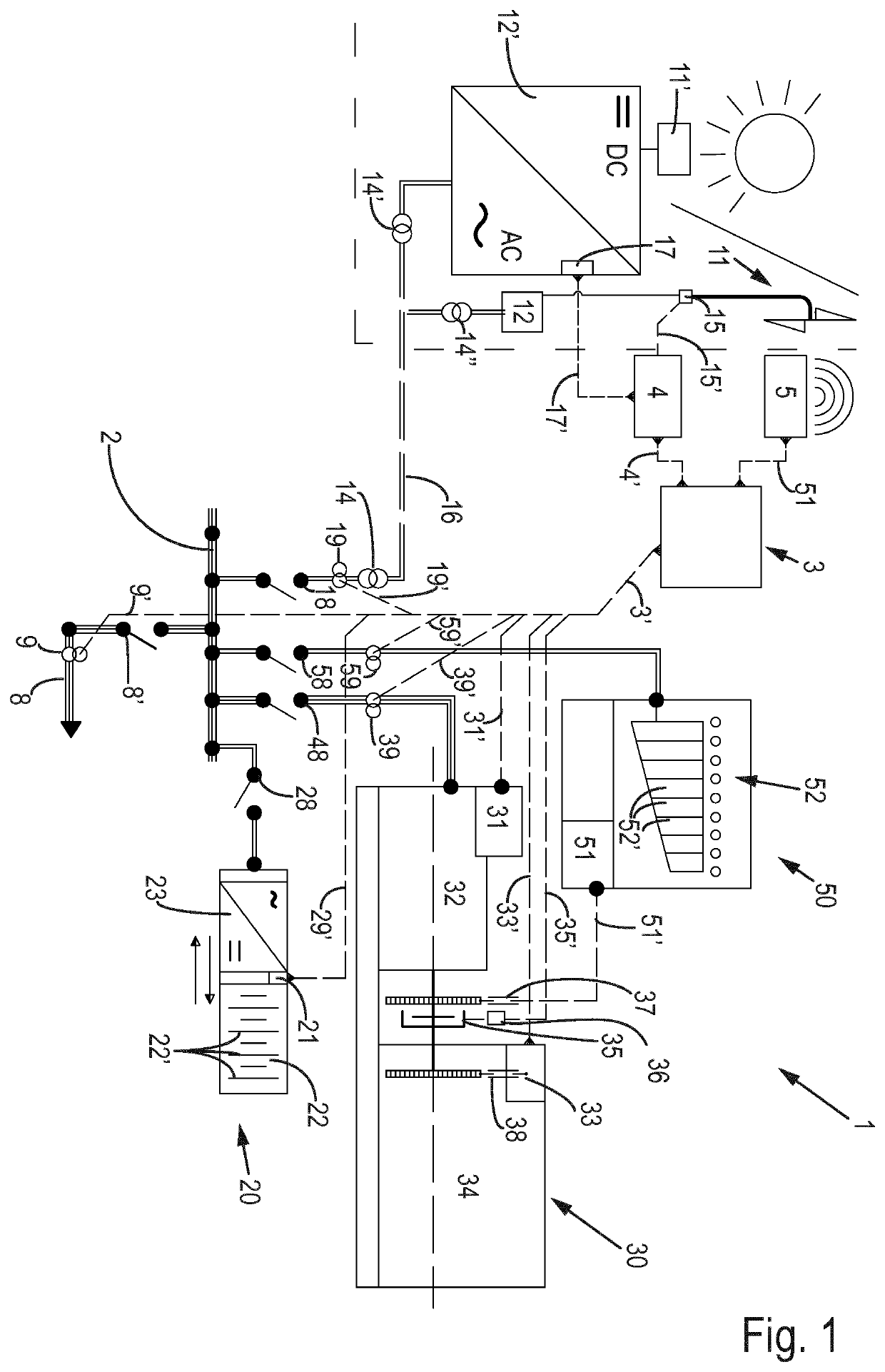
[0061]FIG. 1 relates to a first preferred embodiment of a plant 1 according to the present invention, comprising both required parts and optional parts, the required parts only being limited to parts as identified in the respective dependent and independent claims. A busbar 2 is provided to link the plant with a power grid, preferably an island grid that is preferably solely provided with electrical power from this power plant.

[0062]The plant 1 comprises a plant controller 3, a, preferably battery based, power buffer subsystem 20, generator set subsystem 30, as well as an optional dumpload system 50. The plant controller is provided with an interface controller 4 for controlling a power supply towards the busbar from a renewable power supply system comprising either a wind turbine 11 or a solar energy collector 11′. The interface controller for is intended to be the outer limit of the power plant, being arranged to cooperate with controlling the devices of the renewable energy suppl...


PUM


Abstract

The present invention relates to a method and plant of operating a grid forming power supply plant based on both a renewable energy, such as based on wind energy, solar energy, hydro energy, wave energy, and a carbon based energy, such as carbon based fuel. The grid includes a power input connection from a renewable power supply system and a power input connection from an carbon fuel engine based generator set. The generator set includes an engine for converting the carbon-based energy into motion energy, a generator, such as an alternator, for converting the motion energy into electrical energy, and a clutch for coupling and uncoupling of the engine with the generator. The system also includes a power buffer, such as a battery, subsystem for providing short term grid forming capacity and a plant grid forming controller for controlling grid parameters by means of controlling steps of a method. The plant grid forming controller includes interaction means for interacting with a control unit of the renewable power supply system, interaction means for interacting with a power buffer control unit, and interaction means for interaction with a control unit of the generator set.

Description

CROSS-REFERENCE TO RELATED APPLICATIONS[0001]This application is the United States national phase of International Application No. PCT / EP2019 / 056989 filed Mar. 20, 2019, and claims priority to The Netherlands Patent Application No. 2020629 filed Mar. 20, 2018, the disclosures of which are hereby incorporated by reference in their entirety.BACKGROUND OF THE INVENTIONField of the Invention[0002]The present invention relates to a method for operating a grid forming power supply plant based on both a renewable energy, such as based on wind energy, solar energy, hydro energy, wave energy, and a carbon based energy, such as carbon based fuel. Furthermore, the present invention relates to a plant for operating a grid forming power supply plant based on both a renewable energy, such as based on wind energy, solar energy, hydro energy, wave energy, and a carbon based energy, such as carbon based fuel.Description of Related Art[0003]It is known to provide grid forming power plants for providi...

Claims


Application Information

Patent Timeline
IPC IPC(8): H02J3/32H02J3/38
CPCH02J3/32H02J2300/20H02J3/381H02J3/30H02J3/42H02J2300/10Y02E60/16Y02E70/30Y02E10/76
Inventor VESTESEN, SØREN QVIST
Owner DANVEST ENERGY AS
Why Eureka
Try Eureka