Moment-resistant structure, sustainer and method of resisting episodic loads

a moment-resistant frame and sustainer technology, applied in the direction of girders, building repairs, shock-proofing, etc., can solve the problems of brittle failures at or near connections, severe and widespread damage to moment-resistant frame structures, and large damage to moment-resistant frames

Inactive Publication Date: 2000-01-11
ASCHHEIM MARK AMOS
View PDF39 Cites 112 Cited by
  • Summary
  • Abstract
  • Description
  • Claims
  • Application Information

AI Technical Summary

Benefits of technology

(c) the provision of dissipative zones that are subjected to predominantly biaxial or plane stress conditions, thus preventing conditions of triaxial restraint such as occur at conventional beam-column connections that limit the ductility and strain capacity of the material;
These objects are achieved according to the present invention by providing a structure that includes sustainers in which one or more voids define dissipative zones capable of deforming inelastically. The web of the sustainer has one or more voids of sufficient size, shape, and configuration to reduce the strength of the sustainer having one or more voids sufficiently so that those other members and connections of the structural system that are desired to remain elastic remain substantially elastic. The strength of the voided sustainer thus regulates the forces and stresses that may be imposed on other structural members and connections, and therefore acts as a structural fuse. Therefore, having a plurality of these sustainers having one or more voids prevents stresses elsewhere from reaching intensities that might otherwise cause brittle behavior, fracture, or other undesirable behaviors.

Problems solved by technology

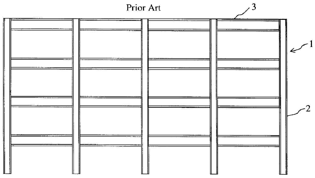
However, the 1994 Northridge earthquake caused unexpected, severe, and widespread damage to steel moment-resistant frame structures in the Los Angeles area.
Much of the damage to steel moment-resistant frames occurred at or near the welded connections between steel girders and columns.
The Japanese also had believed steel structures had superior resistance to earthquakes, but brittle failures at or near connections like those observed in Los Angeles were found after the 1995 earthquake that shook Kobe.
The fractures occurred more often at or near the bottom flange weld, and this is believed to result from difficulties in achieving acceptable welds because physical access to the bottom flange is impeded, and because the floor above the beam protects the top flange and forces the bottom flange to experience larger strength and deformation demands.
Even the best of these have limited deformability, are costly, and may be unreliable.
The reason for this second tenet is concern that the integrity of a column may be compromised if it developed a plastic hinge, and this could jeopardize the stability of the numerous floors that may be supported above.
Steel moment frames were used frequently in earthquake-prone areas, due to market forces and the mistaken belief that this structural system had ample deformation capacity.
Where the strength of the girders is relatively high, an increased likelihood results that plastic hinges develop in the columns.
This unanticipated strength may have the undesirable effect of forcing plastic hinges to develop in the columns.
The concentration of inelasticity into relatively small locations (plastic hinges) requires the material to undergo very large strain demands locally.
Repairs may be so costly as to warrant replacement of the building, or cumbersome rehabilitation.
Improving the quality of the welds and base materials, or increasing the connection strength adequately to promote the development of plastic hinges in the beam away from the connection is expensive.
Details required to relieve triaxial restraint are also costly.
These connections are costly to implement in the field, and affect the stiffness of the building, which in turn affects the required lateral design strength and its displacement response and deformability demand.
Often it is not possible to configure these connections to support beams and girders framing into various sides of a column simultaneously.
But this approach has its disadvantages: (1) it is relatively costly to cut the flange at four locations at each end of the beam; (2) it is not practical to cut the top flanges where floor slabs may be present in the rehabilitation of existing construction; (3) because the plastic hinge zones are set in from the columns, they are subjected to larger deformations to achieve the same displacement of the structure; (4) heavier, more costly beams must be used in order that the cross section having reduced moment capacity provide the system with adequate strength; (5) the removal of flange material reduces the stability of the beam, thereby limiting its deformation capacity; and (6) the asymmetrical removal of flange material, as may happen recognizing the inexactness with which the flange cuts may be executed, may induce instabilities, further limiting the deformation capacity.
This induces high shears on a short segment of the beam, causing it to yield principally in shear under strong lateral motion.
Widespread adoption of the system has been limited by its higher cost and the presence of the diagonal brace, which interferes with floor space utilization.
The cost of this system is bound to increase as it becomes necessary to provide more control over the quality of the welds.
As for flexural yielding systems, the eccentric braced frame imposes relatively high local strain demands because the zones of inelasticity are relatively few in number and small in size.
These three methods all show good performance in the laboratory, but significant cost and architectural accommodations are required to providing the support systems required to use these devices.
These aspects hinder their use in mainstream construction.
The judgement of the engineer is often relied upon, because existing standards are not broad enough in scope and because it is not possible to accurately determine the loss in capacity, if any.
Options are limited, because conventional structural systems are not designed for the replacement of damaged elements.
It is generally easier to replace supplemental damping devices in alternative structural systems, but other aspects hinder their broad acceptance.
(i) the limitation of stress and strain demands, that if excessive, might cause brittle failure of the column flange because of the inferior material properties of relatively thick column flanges by regulating the forces and bending moments resisted at the beam-column connection;

Method used


Image

  • Moment-resistant structure, sustainer and method of resisting episodic loads
  • Moment-resistant structure, sustainer and method of resisting episodic loads
  • Moment-resistant structure, sustainer and method of resisting episodic loads

Examples


Embodiment Construction

FIG. 2 shows a sustainer such as girder 3 connected rigidly to a column 2 at either end of the girder. The girder 3 consists of a web 4 and flange plates 5, 5'. The web 4 is penetrated by a number of voids, such as voids 6a having a circular cross section. A preferred embodiment utilizes a single row of uniform voids, each void having a substantially circular cross section with the voids being substantially centered between the flanges and distributed along the length of the girder.

Consider a steel wide flange beam secured rigidly at its ends to adjacent columns, subjected to loads and deformations imparted only by the columns, and having a point of inflection at midspan. The peak normal stress developed in the flanges at the connection to the columns is desired to be limited to a nominal target valued f.sub.S, also known as the maximum allowable demand, which may be less than the yield strength of the steel material. Because beams of ordinary dimensions have sufficient shear streng...


PUM


Abstract

The present invention relates to a moment-resistant structure, sustainer, and method of construction for deformably resisting episodic loads, particularly those of high intensity. The episodic loads may be due to earthquake, impact, or other intense episodic sources. The structure and sustainer may be in buildings, bridges, or other civil works, land vehicles, watercraft, aircraft, spacecraft, machinery, or other structural systems or apparati. Deformation capacity is enhanced by the use of multiple dissipative zones. Dissipative zones that function in a manner similar to plastic hinges are determined by one or more voids that are located in the web of a sustainer. The one or more voids are of a size, shape, and configuration to assure that the dissipative zones deform inelastically when a critical stress, i.e., a maximum allowable demand, is reached, thereby developing the action of a structural fuse, preventing the occurrence of stress and strain demands sufficient to cause fracture of the connection welds or adjacent heat-affected zones, i.e., preventing the stress and strain demands from exceeding the strength capacity of the connection welds or adjacent heat-affected zones. The sustainers may be removably connected to the remainder of the structure, facilitating their replacement after inelastic deformation. The structure, sustainer, and method of construction may be utilized in new construction and in the rehabilitation of existing construction. Mechanical equipment and utilities may pass through the voids.

Description

1. Field of the InventionThe present invention relates to a moment-resistant structure, sustainer, and method of construction for deformably resisting episodic loads, particularly those of high intensity. The episodic loads may be due to earthquake, impact, or other intense episodic sources. The structure and sustainer may be in buildings, bridges, or other civil works, land vehicles, watercraft, aircraft, spacecraft, machinery, or other structural systems or apparati. The sustainer is a rigid member which resists transverse loading and supports or retains other components of a construction, such as a joist, a beam, a girder, a column, or any member which resists transverse loading. The structure or sustainer may be comprised of metals, such as steel, iron, aluminum, copper, or bronze, or of wood or wood products, or of concrete, plastics, other polymers, fiberglass or carbon fiber composites, ceramics, or other materials or combinations involving these and other materials.2. Descri...

Claims


Application Information

Patent Timeline
Patent Type & Authority Patents(United States)
IPC IPC(8): E04B1/24E04C3/08E04C3/04E04H9/02
CPCE04B1/24E04C3/086E04B2001/2415E04B2001/2448E04B2001/2487E04C2003/0413E04C2003/0417E04C2003/0421E04C2003/0434E04C2003/0452E04C2003/0465
Inventor ASCHHEIM, MARK AMOS
Owner ASCHHEIM MARK AMOS
Why Eureka
Try Eureka