
Alignment of a Needle in an Intradermal Injection Device

a technology for intradermal injection and needle alignment, which is applied in the direction of intravenous devices, etc., can solve the problems of intradermal injection difficulty, failed injection, and lost delivery compound on the surface of the skin

Inactive Publication Date: 2011-09-15
SID TECH LLC +1
View PDF46 Cites 21 Cited by
  • Summary
  • Abstract
  • Description
  • Claims
  • Application Information

AI Technical Summary

Problems solved by technology

Making intradermal injections is difficult and generally requires an experienced nurse or medical professional.
Incorrect placement of the tip of the needle cannula leads to a failed injection.
Incorrect placement of the needle cannula may also puncture the skin again after being inserted into dermis, with the delivered compound being lost on the surface of the skin.
The insertion of the needle at an incorrect angle and / or depth results in a failed intradermal injection.
Intradermal (ID) injection has been considered for immunization in the past, but has generally been rejected in favor of more reliable intramuscular or subcutaneous routes of administration because of the difficulty in making a successful ID injection.
The technique is known to be quite difficult to perform and requires specialized training.
A degree of imprecision in the placement of the injection results in a significant number of false negative test results.
As a result, the Mantoux approach has not led to the use of intradermal injection for systemic administration of substances, despite the advantage of requiring smaller doses of substances.
These devices employ complex constructions that tension the skin by vacuum, expanding the mounting surface prior to the needle insertion.
The main limitation of the systems developed by Alchas et al. is the broad range of deposit depth due to assembly tolerances, needle bevel and the variations in skin properties.
The jet effect further limits the performance when a shallow delivery is attempted.
The lack of suitable devices to accomplish reproducible delivery to the epidermal and dermal skin layers has limited the widespread use of the ID delivery route.
Using conventional devices, ID injection is difficult to perform, unreliable and painful to the subject.
Furthermore, the devices and methods broaden the number of sites suitable for ID injection and make successful ID injections possible with limited training.

Method used


Image

  • Alignment of a Needle in an Intradermal Injection Device
  • Alignment of a Needle in an Intradermal Injection Device
  • Alignment of a Needle in an Intradermal Injection Device

Examples


first embodiment

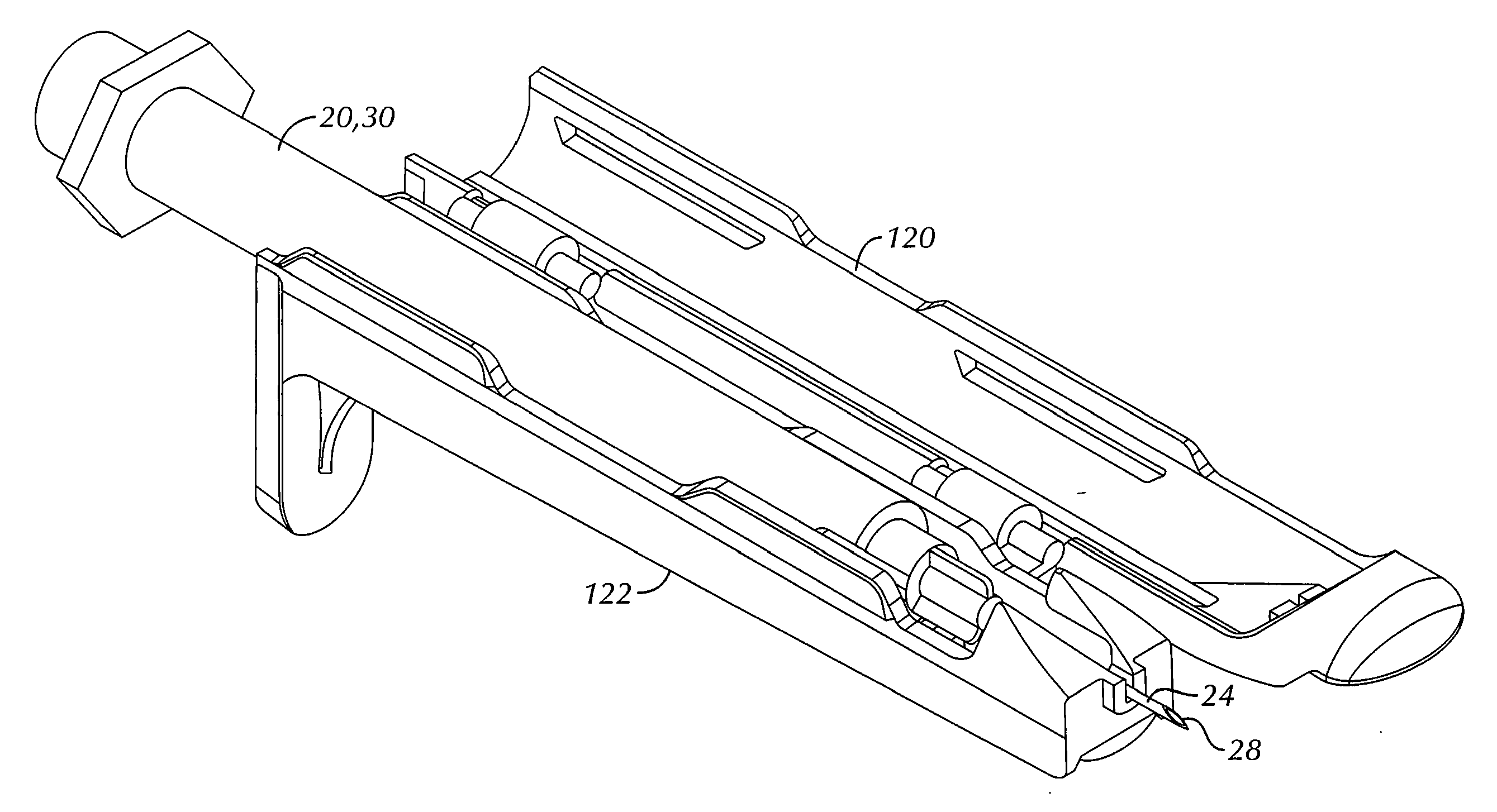
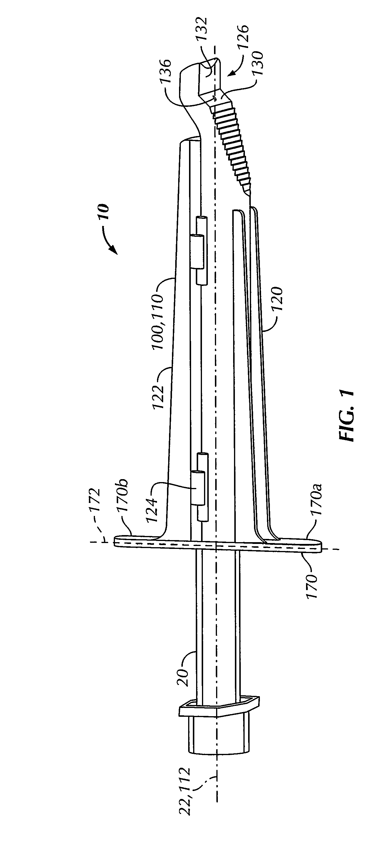
[0035]Referring to the drawings, shown in FIG. 1 is a first presently preferred embodiment of an adapter device 100 for use in combination with a syringe 20 to form an assembly 10 for delivering an intradermal injection. The adapter device 100 comprises a body 110 connectable to the syringe 20. In this first embodiment, the body 110 is formed in a first portion 120 and a second portion 122, the portions 120, 122 being rotatably connectable by one or more hinges 124 and inter-engaging connector tabs 125 and receiving holes 127 (see FIG. 3). The body is preferably formed using conventional polymeric materials, for example polypropylene, using conventional fabrication techniques, for example, injection molding. Other materials and fabrication techniques could also be used.

[0036]The body 110 may be sized and shaped to accept any type of syringe 20, for example a fixed needle style syringe 30 (see FIG. 5), or a Luer lock style syringe (not illustrated) or other standard syringes. The syr...

second embodiment

[0061]More particularly, as illustrated schematically in FIGS. 11A and 11B, a third needle alignment technique is based on providing the single support element 240 having a planar portion 242. With the syringe 20 and second embodiment adapter device 200 fully assembled, the planar portion 242 positions the needle cannula 24 at a known support angle 280 relative to the syringe centerline 22. More particularly, the single support element 240 supports the needle cannula 24 at the support point 290 which is offset from the syringe centerline 22 in a vertical plane 248 substantially perpendicular to the planar portion of the second primary skin contacting surface 232. The offset can be either toward the second primary skin contacting surface 232, or away from it (that is, either in a positive or negative y direction, (the y direction being as indicated in FIGS. 11A and 11B)).

[0062]In order to appropriately control the depth of the injection, the planar portion of the second primary skin ...


PUM


Abstract

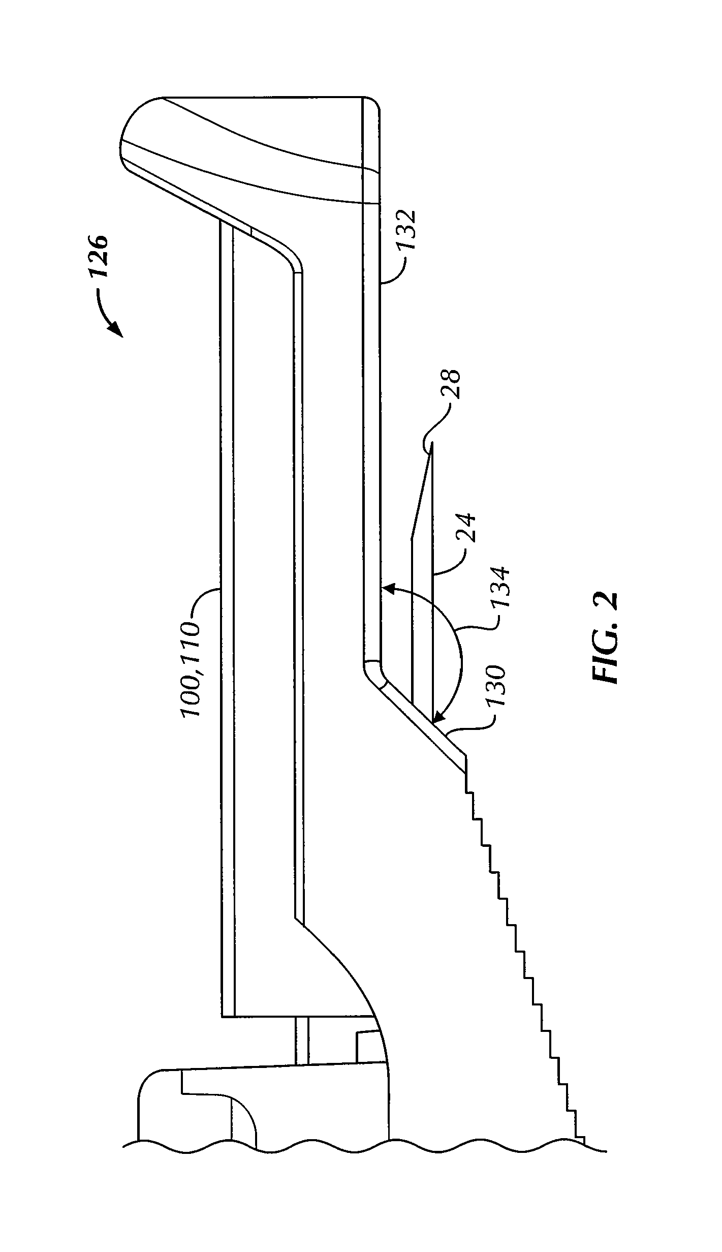
An adapter device (100, 200) for use in combination with a syringe (20) to form an assembly (10) for delivering an intradermal injection. The adapter device comprises a body (110, 210) which is connectable to the syringe. A second primary skin contacting surface (232) is positioned at a distal end (126, 226) of the body. At least one support element (140, 150, 240) is connected to the body. With the assembly in an assembled condition, the at least one support element supports a needle cannula (24) connected to the syringe. The needle cannula is supported by the at least one support element intermediate a base (26) and a tip (28) of the needle cannula. At least a terminal portion of the needle cannula extends axially in a direction substantially parallel to at least a planar portion of the second primary skin contacting surface.

Description

BACKGROUND OF THE INVENTION[0001]The invention relates to devices for delivery of intradermal injections generally, and more particularly to an adapter device combinable with a standard syringe to form an assembly for delivery of an intradermal injection.[0002]Intradermal injections are used for delivering a variety of diagnostic and treatment compositions into a patient. Substances may be injected intradermally for diagnostic testing, such as to determine a patient's immunity status against tuberculosis and the status of allergic diseases. Vaccines, drugs and other compounds may also be delivered intradermally. In many instances, intradermal delivery is preferred because it generally requires a smaller volume dose of the diagnostic or treatment compound than other delivery techniques. An intradermal injection is made by delivering the substance into the epidermis and upper layer of the dermis. There is considerable variation in the skin thickness, both between individuals and withi...

Claims


Application Information

Patent Timeline
IPC IPC(8): A61M5/46
CPCA61M5/3216A61M5/46A61M5/425A61M5/3287
Inventor TSALS, IZRAILHARVEY, DARRELL
Owner SID TECH LLC
Learn More