
Method and apparatus for detecting fluorescence emitted by particle-bound fluorophores confined by particle traps

Inactive Publication Date: 2011-09-22
NAT RES COUNCIL OF CANADA
View PDF3 Cites 20 Cited by
  • Summary
  • Abstract
  • Description
  • Claims
  • Application Information

AI Technical Summary

Benefits of technology

[0010]The present invention offers a new approach which will enable the efficient use of particle confinement strategies implemented in detection devices such as point-of-care μTAS diagnostic platforms. This new approac

Problems solved by technology

This optical system, while providing an excellent detection limit, also requires a time-consuming scanning step and associated hardware (i.e. high precision translation stages, motors and control electronics), which are major drawbacks.
However, this detection technique requires time-consuming preliminary procedures (i.e. incubation of the sensor array followed by rinsing and drying steps).
Moreover, the sensitivity of absorbance (or transmission) measurements is generally limited and strongly depends on the stability of the

Method used


Image

  • Method and apparatus for detecting fluorescence emitted by particle-bound fluorophores confined by particle traps
  • Method and apparatus for detecting fluorescence emitted by particle-bound fluorophores confined by particle traps
  • Method and apparatus for detecting fluorescence emitted by particle-bound fluorophores confined by particle traps

Examples


example 1

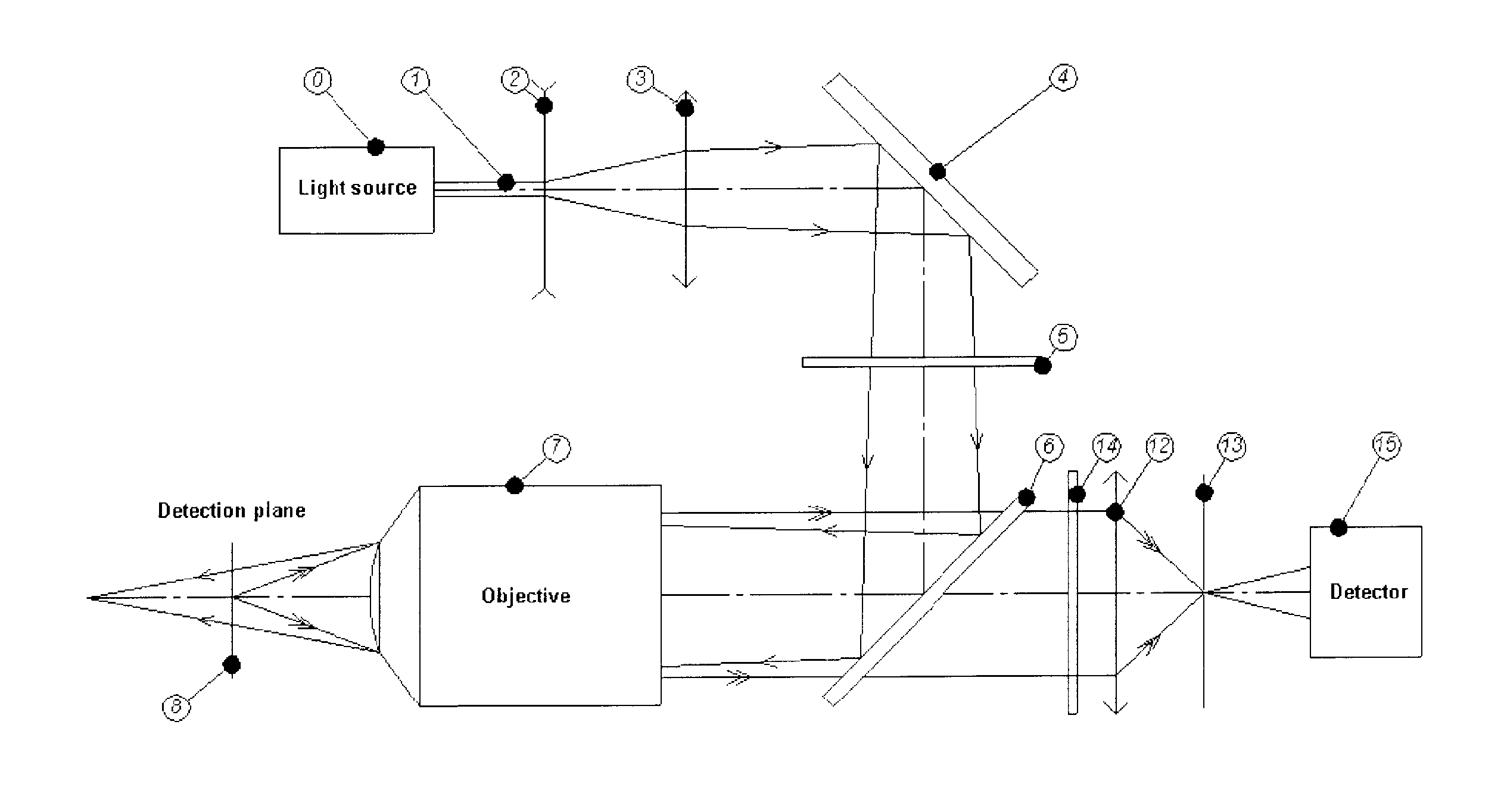
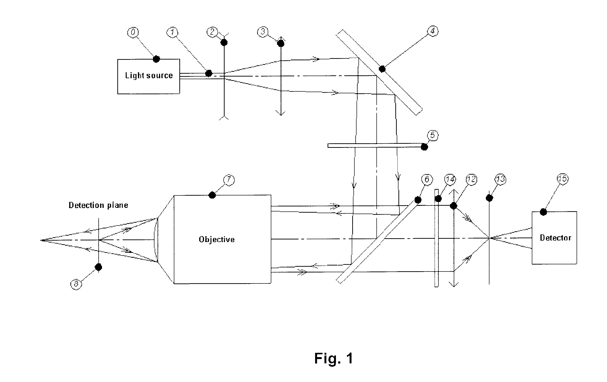
[0098]A solid state laser diode emitting at 405 nm (PointSource, iFLEX2000) used as a light source 0 is coupled to a pigtailed single mode optical fiber equipped with a collimator at the fiber end (PointSource, KineFLEX) that produces a 1 mm diameter (at 1 / e2) diffraction limited beam 1 with a divergence angle of less than 0.1 mrad.

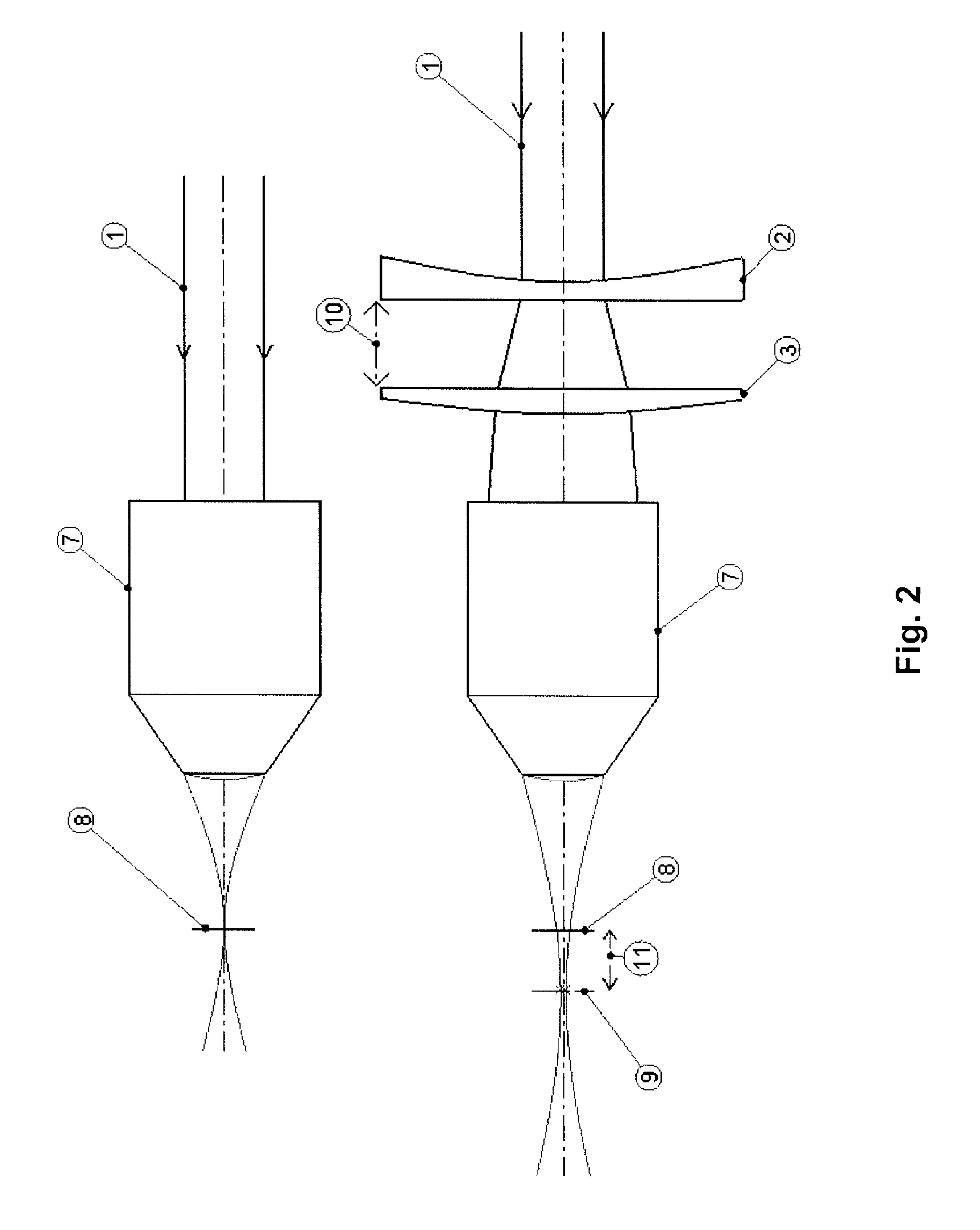
[0099]The divergence of the beam is induced by means of a pair of lenses 2, 3 (Thorlabs, f=−30 mm, LC4252 and f=75 mm, LA4725) and controlled through the spacing of the lenses. For the present demonstration, lenses were separated by 41 mm. According to FIG. 4, a lens pair separation 10 of 41 mm generates a 75 μm beam footprint (radius measured at 1 / e2) at the focal plane 8 thus enabling the whole μ-EMT illumination. With such parameters, 70% of beam energy is contained within the μ-EMT diameter.

[0100]The μ-EMT consist of 75-μm diameter planar micron-scale gold conductors supported on SiO2 / Si wafers, a design previously described by Dubus et al.

[0101]The l...

example 2

[0108]Another specific example of components usable for the selective detection of minute amounts of target genomic DNA from gram positive bacteria-containing samples, as in the illustrated embodiments of the invention includes:

[0109]A microfluidic system 20 having a combination of two different particle traps, namely a μ-EMT 22 and a weir 36 has been used for this series of experiments. The PDMS microfluidic channels 38 are 100 microns wide, 20 microns high, and the weir leaves a shallow gap in the microfluidic channel of 2 microns in height, enabling to trap small paramagnetic particles of 2.8 microns diameter while allowing the sample solution to flow through the weir.

[0110]Samples of initially approx. 500 particles grafted with probe DNA (=ssDNA sequence complementary to target ssDNA sequence) and a fluorescent biosensor were prepared and pumped into the microfluidic system through sample inlet 32 using a syringe pump 40. Particles were trapped at the weir while the solution was...

example 3

[0112]Another specific example of components usable for the selective detection of minute amounts of target genomic DNA from an endospore-forming bacteria-containing samples, as in the illustrated embodiments of the invention includes:

[0113]A microfluidic system, sample preparation, sample handling, data acquisition and data analysis procedures as described in Example 2, with the exception that only one replica per sample (Specific Sequence, Non-specific Sequence and Reference) was tested.

[0114]These results, shown in FIG. 20, highlight the very high sensitivity (i.e. approx 500 genomic DNA copies detected in the particle trap) and selectivity of such an approach (good contrast with respect to the Non-specific Sequence and Reference samples). It also shows the possibility to detect, with comparable performance, different genomic DNA sequences originating from different samples. It finally shows the potential to perform rapid tests on limited sample volumes / amounts with reliable resu...


PUM


Abstract

A method of detecting a fluorescence signal emitted by fluorophores bound to particles confined in a particle trap, includes an objective lens having a focal plane, which is normally the focal plane for incident collimated light. The particle trap is typically located in the focal plane, and a beam of excitation light is directed via the objective lens onto the confined particles in the trap. The excitation light is in the form of a divergent beam coming to focus at a plane displaced from the focal plane. The divergent beam has a spot diameter at the focal plane determined by the divergence of the beam. The fluorescent light emitted by the fluorophores is detected with a confocal detector.

Description

FIELD OF THE INVENTION[0001]The present invention relates to the detection of signals emitted by molecules bound to particles, and in particular to a method and apparatus for reading the fluorescence signal emitted by fluorescent molecules bound to magnetic particles which are confined in a small volume by means of a particle trap, such as a Micro-ElectroMagnetic Trap (μ-EMT).BACKGROUND OF THE INVENTION[0002]In the paper by Lee (Lee et al. 2001), Lee, C. S., H. Lee, et al. (2001). “Microelectromagnets for the control of magnetic nanoparticles.”Applied Physics Letters 79(20): 3308-3310, the possibility of efficiently manipulating and controlling the motion of magnetic particles using microfabricated electromagnets is discussed. These devices not only produce strong local magnetic fields but can also be easily switched on and off by controlling the electrical current that flows through these devices.[0003]Magnetic separation technology based on surface-functionalized magnetic micro- o...

Claims


Application Information

Patent Timeline
IPC IPC(8): G01N21/64
CPCG02B21/16G01N21/645
Inventor BOUDREAU, DENISGRAVEL, JEAN-FRANCOISVOISIN, BENOITLE DROGOFF, BORISVERES, TEODOR
Owner NAT RES COUNCIL OF CANADA
Learn More