
Temperature compensated thin film acoustic wave resonator

a thin film acoustic wave and resonator technology, applied in the field of acoustic wave resonators, can solve the problems of reducing the elastic constant of the material, concomitantly reducing the acoustic velocity, and ignoring the need of the ar

Active Publication Date: 2011-09-22
AVAGO TECH INT SALES PTE LTD
View PDF5 Cites 43 Cited by
  • Summary
  • Abstract
  • Description
  • Claims
  • Application Information

AI Technical Summary

Benefits of technology

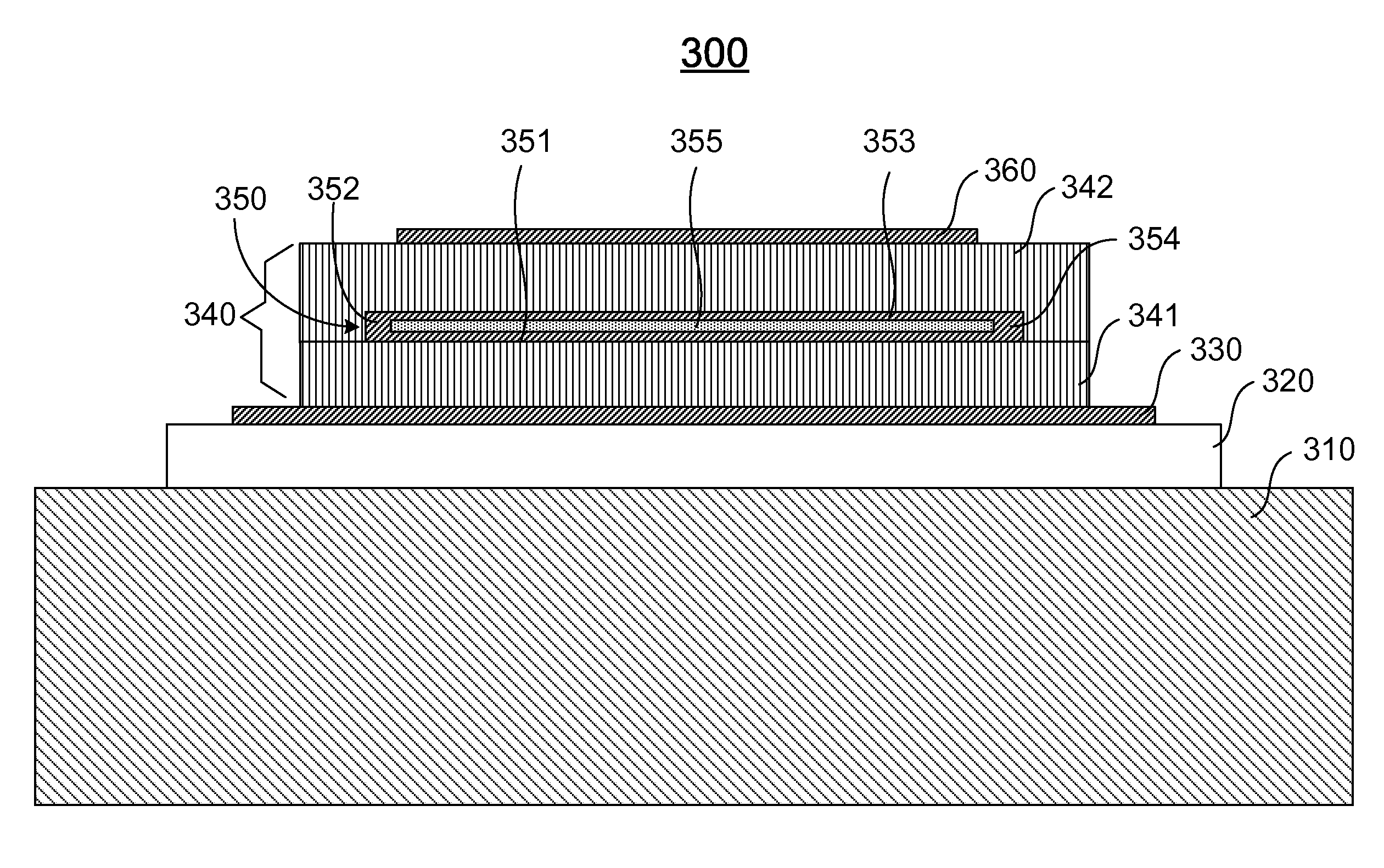
[0021]In one embodiment, the step of forming the second electrode layer of the composite structure comprises the steps of forming one or more vias or trenches in the temperature compensation layer, depositing and patterning a first conductive material on the temperature compensation layer to fill the one or more vias or trenches therein such that the first conductive material filled in the one or more vias or trenches is in contact with the first electrode layer, planarizing the deposited and patterned first conductive material until the top surface of the temperature compensation layer is exposed, and depositing and patterning a second conductive material on the planarized temperature compensation layer to form the second electrode layer such that the second electrode layer is connected to the first electrode layer. The first and second conductive materials are identical or different.
[0022]In one embodiment, the one or more vias or trenches formed in the temperature compensation layer have a cross-sectionally tapered shape.

Problems solved by technology

A decrease in the inter-atomic force results in a decrease in the elastic constant of the material with a concomitant decrease in the acoustic velocity.
Hence, a heretofore unaddressed need exists in the art to address the aforementioned deficiencies and inadequacies.

Method used


Image

  • Temperature compensated thin film acoustic wave resonator
  • Temperature compensated thin film acoustic wave resonator
  • Temperature compensated thin film acoustic wave resonator

Examples


Embodiment Construction

[0049]The present invention is more particularly described in the following examples that are intended as illustrative only since numerous modifications and variations therein will be apparent to those skilled in the art. Various embodiments of the invention are now described in detail. Referring to the drawings, like numbers indicate like components throughout the views. As used in the description herein and throughout the claims that follow, the meaning of “a”, “an”, and “the” includes plural reference unless the context clearly dictates otherwise. Also, as used in the description herein and throughout the claims that follow, the meaning of “in” includes “in” and “on” unless the context clearly dictates otherwise.

[0050]The terms used in this specification generally have their ordinary meanings in the art, within the context of the invention, and in the specific context where each term is used. Certain terms that are used to describe the invention are discussed below, or elsewhere ...


PUM

PropertyMeasurementUnit
temperatureaaaaaaaaaa
temperature coefficient of frequencyaaaaaaaaaa
structureaaaaaaaaaa

Abstract

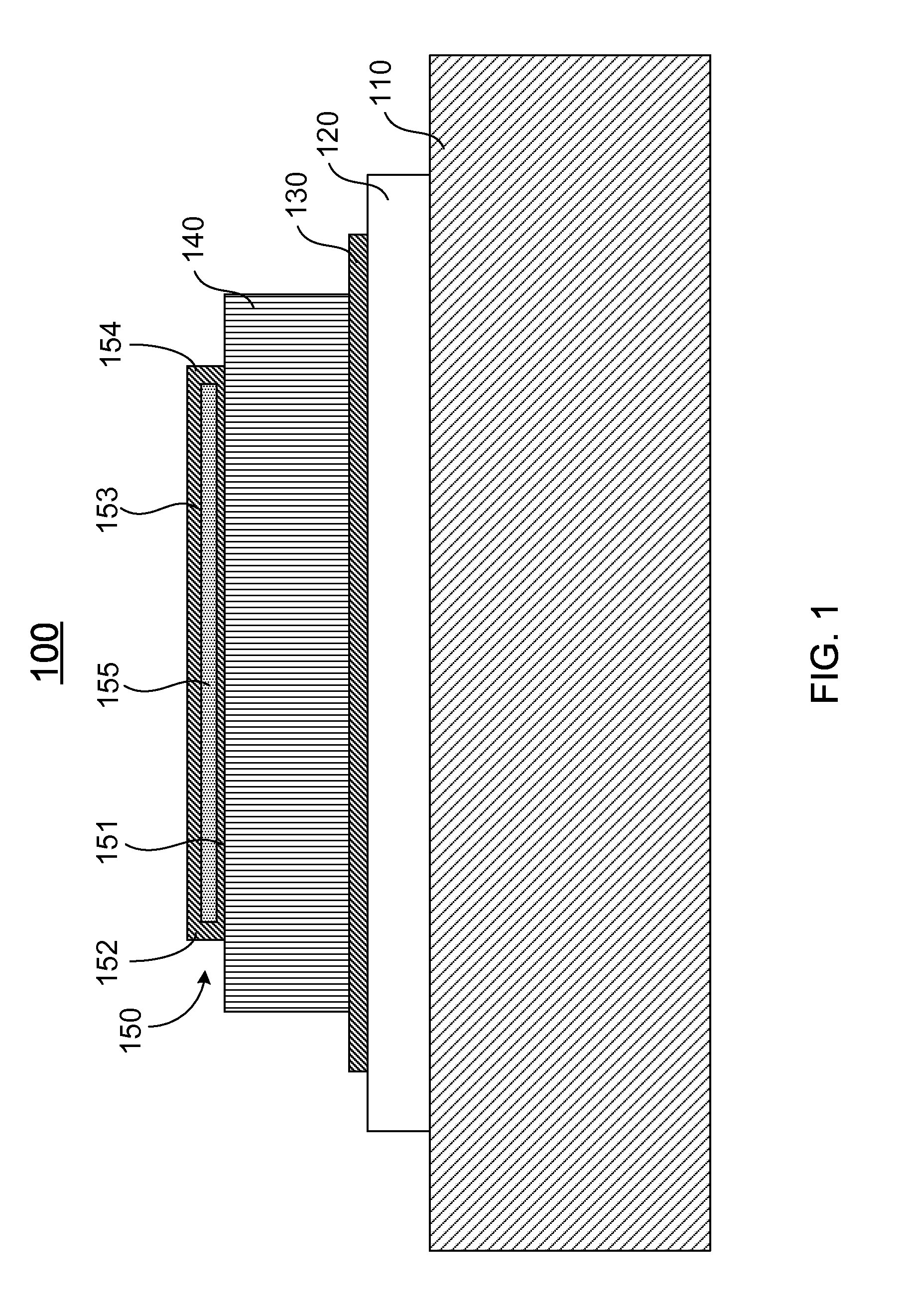
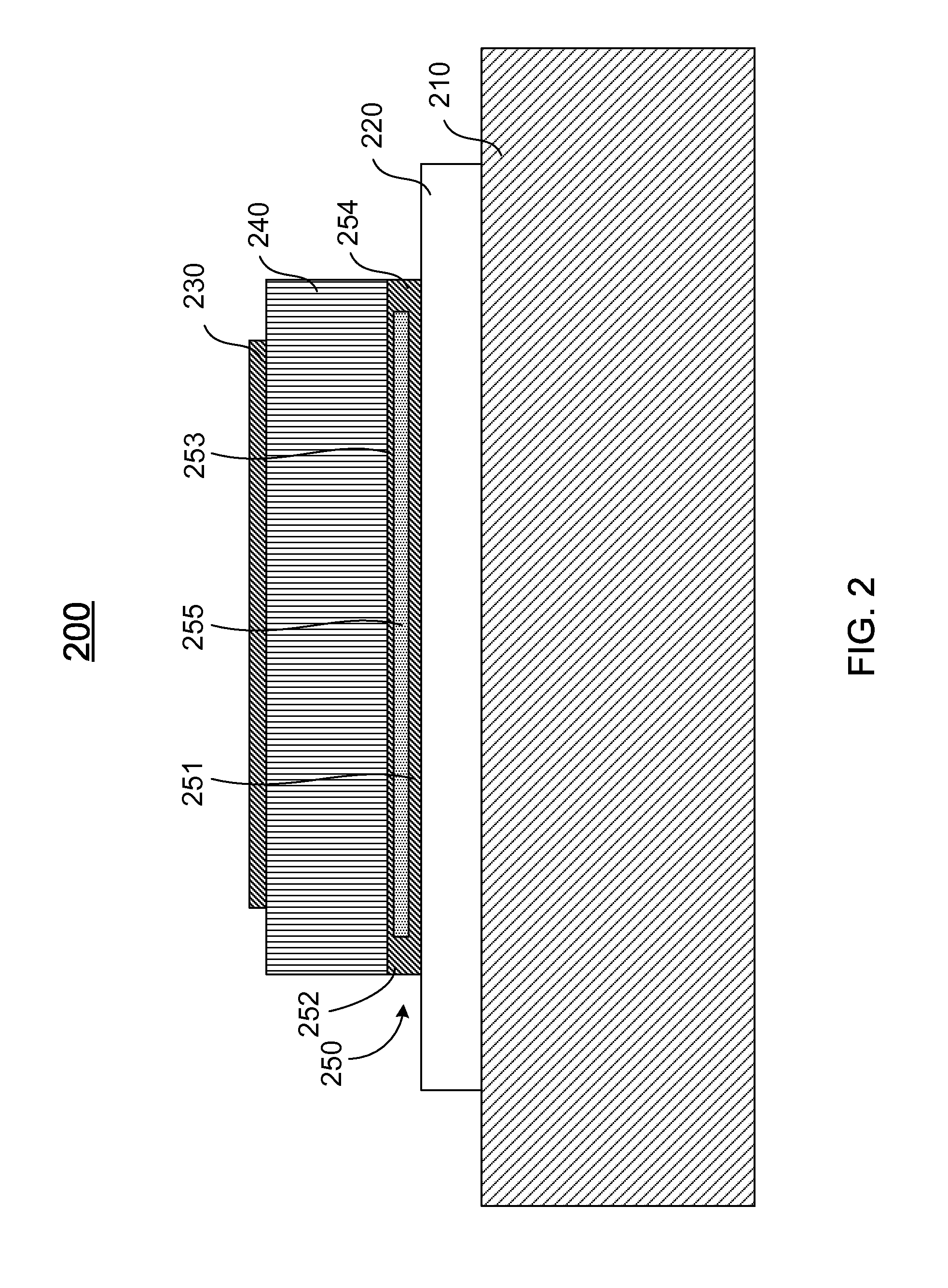
The present invention in one aspect relates to an acoustic wave resonator having an acoustic reflector, a piezoelectric layer, a composite structure having a first electrode, a temperature compensation layer formed on the first electrode, having one or more vias or trenches formed therein, and a second electrode formed on the temperature compensation layer and electrically connected to the first electrode at least through the one or more vias or trenches, and a third electrode, where the composite structure is disposed under the piezoelectric layer, on the piezoelectric layer, or inside the piezoelectric layer.

Description

FIELD OF THE INVENTION[0001]The present invention relates generally to an acoustic wave resonator, and more particular to a thin film bulk acoustic wave (BAW) resonator that utilizes a composite structure having a temperature compensation layer formed such that no electrical field exists therein so as to improve the temperature stability of the BAW resonator and methods of manufacturing the same.BACKGROUND OF THE INVENTION[0002]Radio frequency (RF) front-end circuits, such as transceivers, power amplifiers, and passives are increasingly used for wireless communication. The front-end passives include RF filters. RF front-end filters consisting of bulk acoustic wave (BAW) resonators have been proven to have a number of advantages regarding quality factor, power handling, ESD robustness and size over other technologies, such as surface acoustic wave (SAW) devices and ceramic filters. Temperature stable oscillator incorporating BAW resonator has also been demonstrated to be well suited ...

Claims


Application Information

Patent Timeline
Patent Type & Authority Applications(United States)
IPC IPC(8): H03H9/64H04R17/00H04R31/00
CPCH04R17/00Y10T29/49005Y10T29/42H04R31/00
Inventor ZHANG, HAO
Owner AVAGO TECH INT SALES PTE LTD
Learn More