Bifocal lens and bifocal eyeglasses

a technology of bifocal lenses and bifocal eyeglasses, applied in the field of bifocal lenses, can solve the problems of high production costs of bifocal lenses, vibration may be felt, object may be seen as being distorted, etc., and achieve the effect of reducing costs

Active Publication Date: 2011-09-22
KUROSAKI HISAYOSHI
View PDF1 Cites 0 Cited by
  • Summary
  • Abstract
  • Description
  • Claims
  • Application Information

AI Technical Summary

Benefits of technology

[0036]According to the present invention described above, a bifocal lens and bifocal eyeglasses can be realized by which strangeness felt during using a near-vision region is removed, a place according to the purpose of use can clearly be selected, and costs are reduced.

Problems solved by technology

However, regarding the progressive lens, the production costs thereof are high, and also not a little disadvantage may occur at the time of use.
First, in the progressive lens, when the user looks through the intermediate region in which the eyeglass degree changes progressively, an object may be seen as being distorted, or a vibration may be felt when the face is swung in the right-and-left direction.
In particular, since the user cannot recognize the boundary line of the near-vision region and the intermediate region, the aforementioned disadvantage is inevitable until the user becomes fully accustomed to the use of the progressive lens, whereby even an accident of falling down may occur.
This disadvantage is conspicuous at the time of work when the user must repeatedly look at the far area and the near area.
For example, this disadvantage will be a problem not only at the time of highly dangerous mechanical operation that is executed at the construction site or production site but also at the time of driving a general automobile or at the time of fishing involving attachment and removal of a bait.
Therefore, when the user must carefully read sentences that continue to be long in the lateral direction for a long period of time, or when a monitoring activity must be carried out widely by closely watching down to the details of a large screen in the right-and-left direction, the disadvantage will be conspicuous.

Method used


Image

  • Bifocal lens and bifocal eyeglasses
  • Bifocal lens and bifocal eyeglasses
  • Bifocal lens and bifocal eyeglasses

Examples


Embodiment Construction

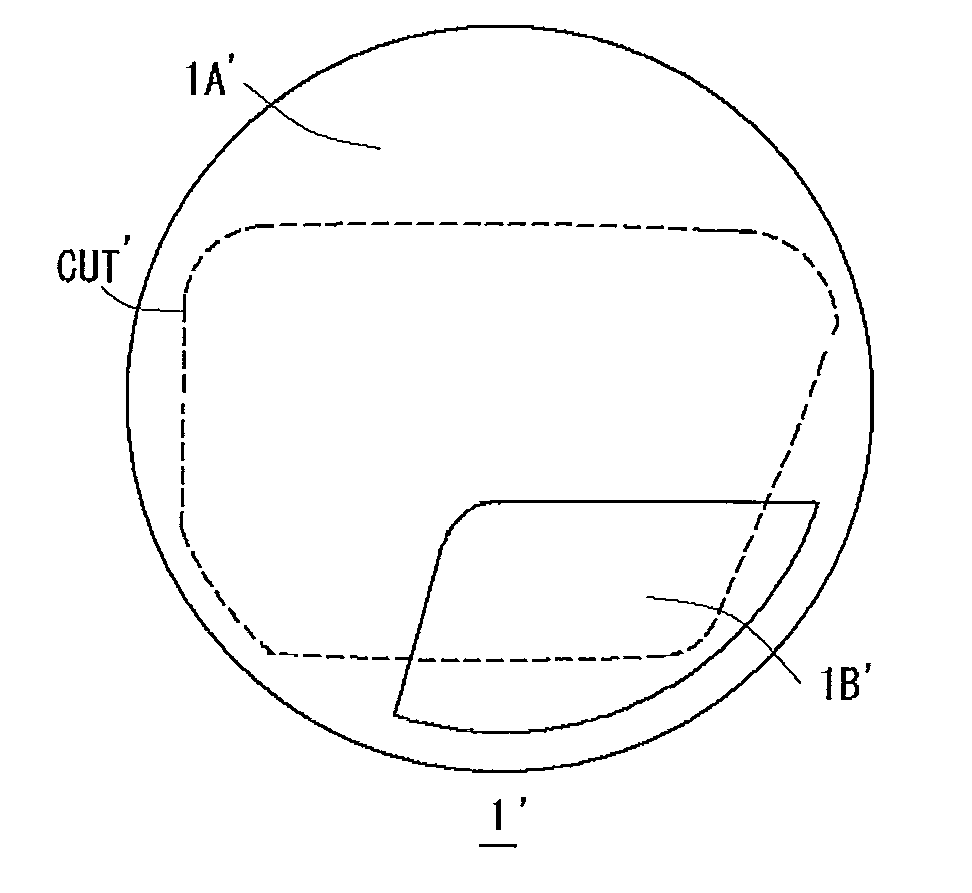
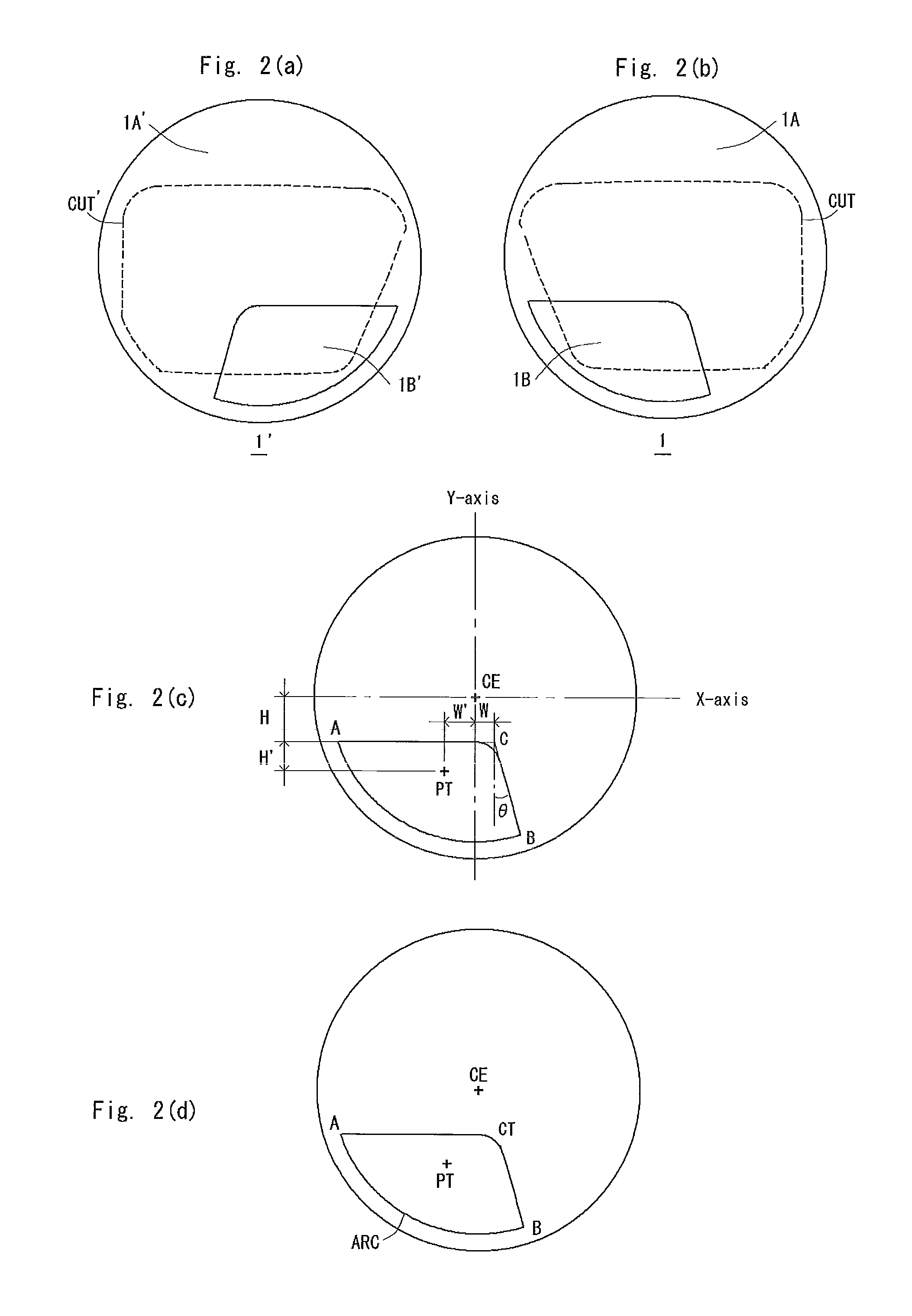
[0047]Hereafter, the present invention will be described in detail with reference to the embodiments. FIG. 2(b) is a front view showing a substrate lens 1 for a left eye that has been molded generally in a disk shape. This substrate lens 1 is cut out along a broken line CUT to accord to the pupil position of a user and the shape of an eyeglass frame, and is mounted on the left eye part of the eyeglass frame. Here, FIG. 2(a) shows a substrate lens 1′ for a right eye, and is constructed to be symmetric to the substrate lens 1 for the left eye relative to the right-and-left direction.

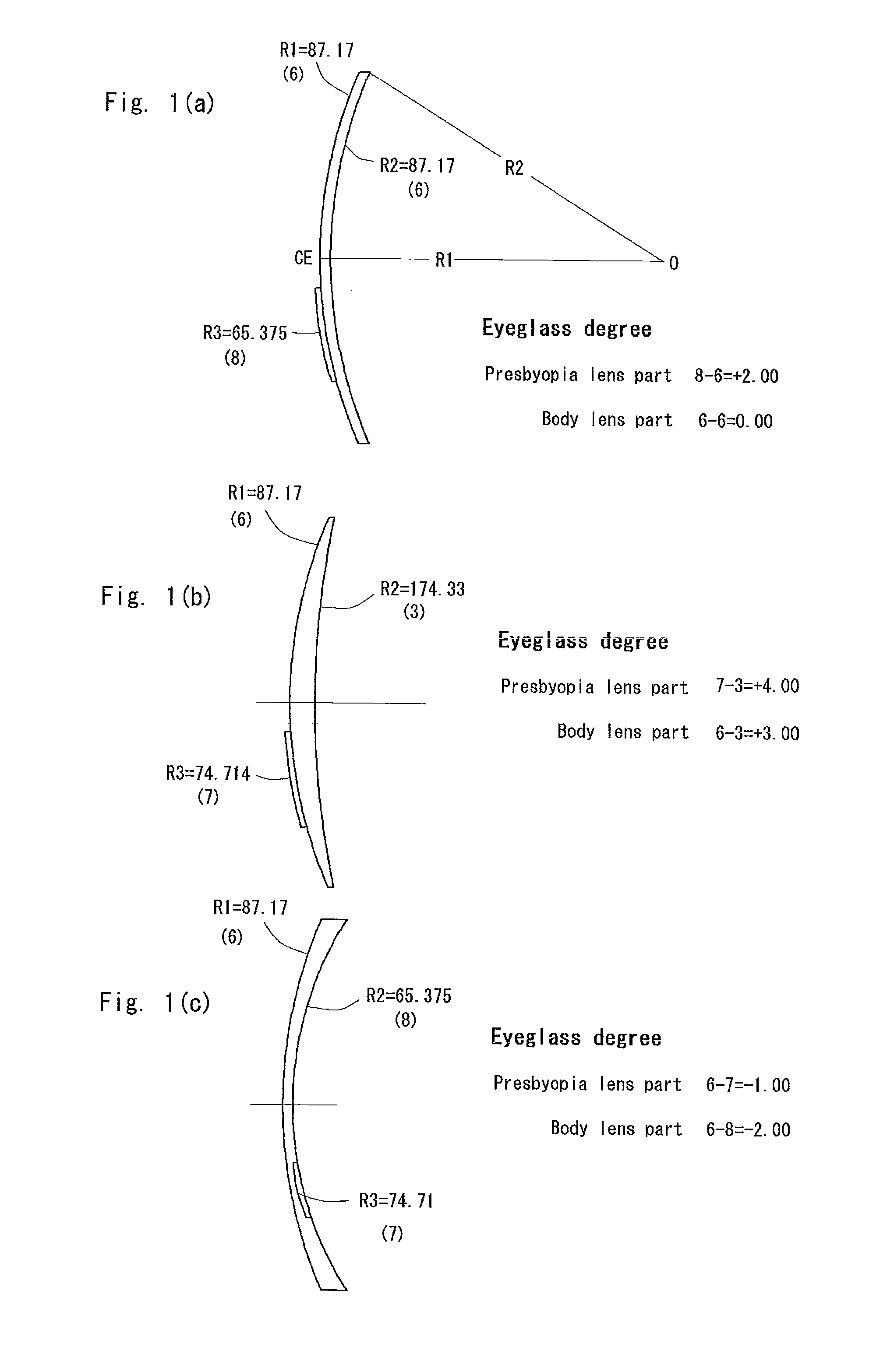
[0048]As shown in FIGS. 2(b) to 2(d), the substrate lens 1 for the left eye is constructed in such a manner that a presbyopia lens part 1B is disposed in the lower left portion of a body lens part 1A. The body lens part 1A is a part for looking at something in the distance, and is formed of an outer spherical surface having a first radius of curvature R1 and an inner spherical surface having a second radiu...


PUM


Abstract

A bifocal lens and bifocal eyeglasses by which strangeness felt during using a near-vision portion is removed, a place according to the purpose of use can clearly be selected, and costs are reduced. The bifocal lens for eyeglasses is constituted of a single material with a uniform refractive index and is provided with a lens for presbyopia (1B) used for looking at something near at a portion of a body lens part (1A) used for looking at something in the distance. The lens for presbyopia (1B) is formed of an upper side which is generally horizontal when used, a lateral side on the ear side which continues to the upper side and expands toward the ear, and a lower side parallel to the peripheral shape of the lower side of an eyeglass frame to be generally circular-arc or generally rectangular as a whole. The upper side and the lateral side form a generally straight boundary line which can be recognized by a user.

Description

TECHNICAL FIELD[0001]The present invention relates to a bifocal lens in which a user can definitely recognize which one of the bifocal lens the user is currently using, and the field of view for near vision in the right-and-left direction is wide, as well as to bifocal eyeglasses using the same.BACKGROUND ART[0002]As a lens for current bifocal eyeglasses, a progressive lens is widely known. The progressive lens is also referred to as “no-line bifocal lens”, where a far-vision region for looking at something in the distance, a near-vision region for looking at something near (presbyopia part), and an intermediate region are disposed in one lens.[0003]The intermediate region is a region in which, from diopter power (hereafter referred to as eyeglass degree) of the far-vision region to the eyeglass degree of the near-vision region, the eyeglass degree is progressively changed. For example, refractive power is changed by a method disclosed in Patent Document 1.[0004]Patent Document 1: J...

Claims


Application Information

Patent Timeline
Patent Type & Authority Applications(United States)
IPC IPC(8): G02C7/06
CPCG02C7/06
Inventor KUROSAKI, HISAYOSHITSUTSUMI, TAKASHI
Owner KUROSAKI HISAYOSHI
Why Eureka
Try Eureka