Keyless/grooveless foil bearing with fold over tab

a foil bearing and fold-over technology, applied in the direction of bearings, shafts and bearings, rotary bearings, etc., can solve the problems of reducing the useful life of the bearing assembly, misalignment between various rotating and stationary parts within the assembly, and complex application

Inactive Publication Date: 2011-09-22
GM GLOBAL TECH OPERATIONS LLC
View PDF8 Cites 10 Cited by
  • Summary
  • Abstract
  • Description
  • Claims
  • Application Information

AI Technical Summary

Benefits of technology

[0009]Concordant and consistent with the present invention, an improved air foil bearing assembly is disclosed, comprising a bearing housing having an axially extending bore therein; a shaft arranged within the bore for relative coaxial rotation with respect to the bearing housing, the shaft cooperating with the bearing housing to define an annular gap therebetween; a foil assembly disposed in the annular gap, the foil assembly further comprising at least one foil having at least one laterally extending tab, the tab adapted to be received in and extend axially from the annular gap and adapted to be bent into frictional contact with an outer surface of the bearing housing to militate against axial movement of the foil.

Problems solved by technology

Even though the principle of an air bearing is simple, application is complex.
Any eccentricity in the shaft, or friction within the bearings, may cause shaft deflection and / or shaft thermal expansion that could exceed the running clearance, thereby reducing the useful life of the bearing assembly.
In addition, damping is required to suppress any whirl instability, and there can be misalignment between various rotating and stationary parts within the assembly.
When the shaft is airborne, the friction loss due to shaft rotation is extremely small.

Method used


Image

  • Keyless/grooveless foil bearing with fold over tab
  • Keyless/grooveless foil bearing with fold over tab
  • Keyless/grooveless foil bearing with fold over tab

Examples


Embodiment Construction

[0019]The following detailed description and appended drawings describe and illustrate various exemplary embodiments of the invention. The description and drawings serve to enable one skilled in the art to make and use the invention, and are not intended to limit the scope of the invention in any manner. In respect of the methods disclosed, the steps presented are exemplary in nature, and thus, the order of the steps is not necessary or critical.

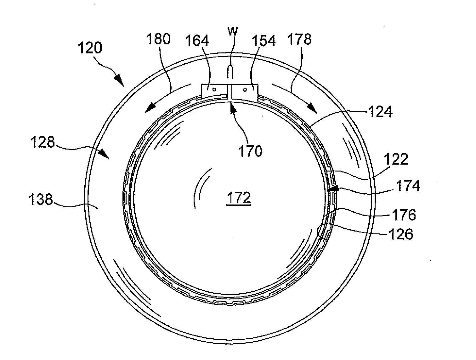
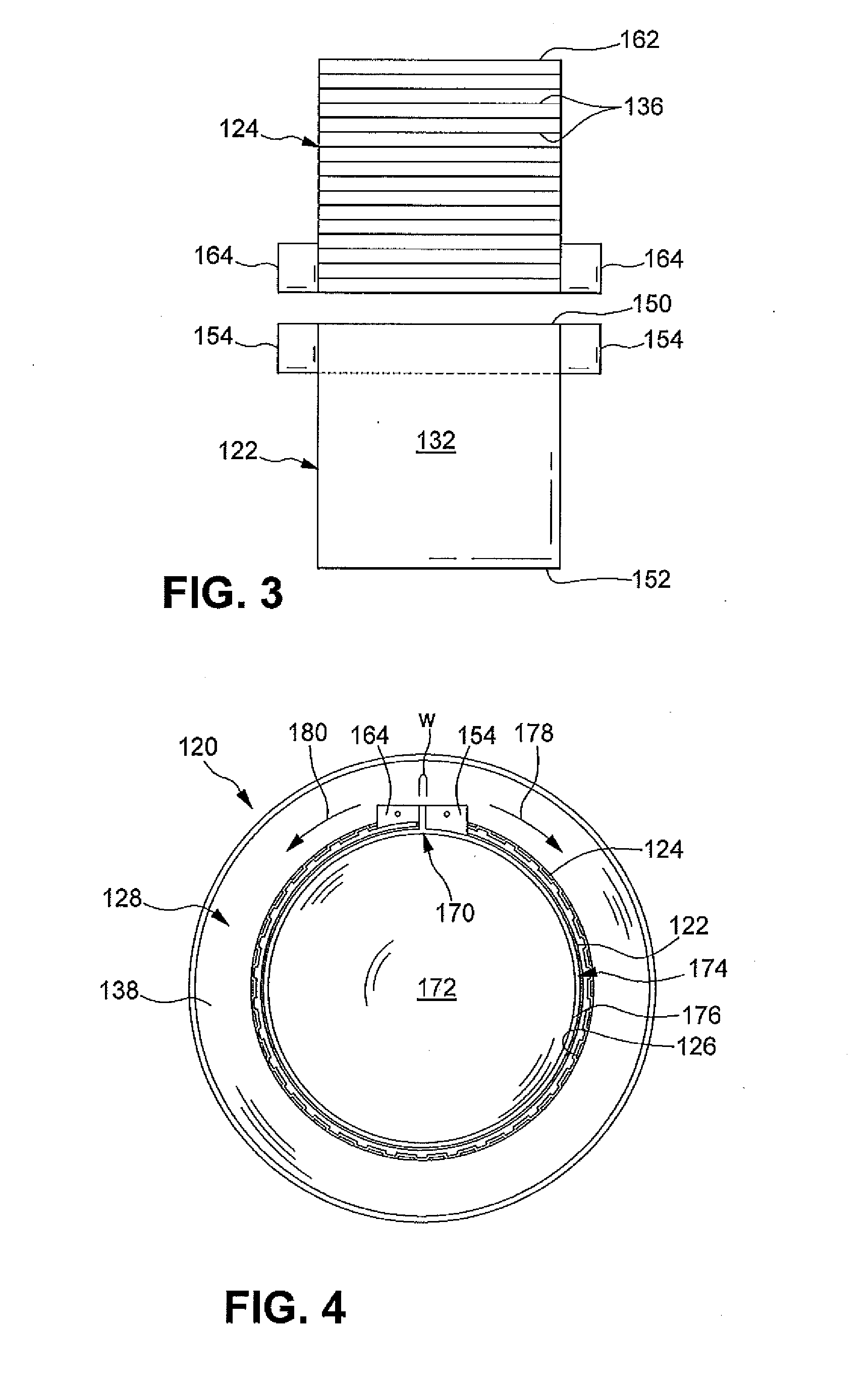
[0020]FIG. 3 illustrates a top foil 122 and a corrugated or “bump” foil 124 of an air foil bearing. As in the prior art, both the top foil 122 and the bump foil 124 are separately stamped from sheet metal to have a desired thickness. At least an inner surface 132 of the top foil 122 is typically coated with a solid film lubricant to provide low contact friction between a rotating shaft 172 shown in FIG. 4. and the inner surface 132 of the top foil 122. The corrugations 136 may be formed in the bump foil 124 as part of the stamping process, o...


PUM


Abstract

An improved air foil bearing assembly is disclosed. The air foil bearing assembly includes a bearing housing having an axially extending bore therein and a shaft arranged within the bore for relative coaxial rotation with respect to the bearing housing. The shaft cooperates with the bearing housing to define an annular gap therebetween. A foil assembly is disposed in the annular gap, including at least one foil having at least one laterally extending tab. The tab is adapted to be received in and extend axially from the annular gap and is further adapted to be bent into frictional contact with an outer surface of the bearing housing to militate against axial movement of the foil.

Description

FIELD OF THE INVENTION[0001]The invention relates to foil air bearings supporting a rotating shaft of a variety of high-speed rotating systems.BACKGROUND OF THE INVENTION[0002]Foil air bearings are known for use with high-speed air rotating shafts. A machine with foil air bearings is more reliable than one with rolling element bearings because it requires fewer parts to support the rotating assembly and needs no lubrication. In operation, an air / gas film between a bearing and a rotating shaft protects the foil bearing itself from wear. The bearing surface is in contact with the shaft only when the machine starts and stops, and a coating on the foils limits wear at those times.[0003]The principle of an air bearing, whether of the journal or thrust type, is simple. When two surfaces form a wedge and one surface moves relative to the other, pressure is generated between the surfaces due to the hydrodynamic action of the fluid carrying the load. In a journal bearing, the shaft deflects ...

Claims


Application Information

Patent Timeline
Patent Type & Authority Applications(United States)
IPC IPC(8): F16C32/06
CPCF16C32/0603F16C32/0607F16C43/02F16C17/024
Inventor FLORA, BRIAN S.CLARK, STEVEN L.SIENKOWSKI, JON R.RUCHNEWITZ, STEPHAN M.
Owner GM GLOBAL TECH OPERATIONS LLC
Why Eureka
Try Eureka