Dental prosthesis

a dental prosthesis and implant technology, applied in the field of dental prosthesis, can solve the problems of high strain on the implant head, low reliability, and fast loss of marginal bone tissue before the function stage, and achieve the effect of reducing or preventing annual bone mass loss and preventing the loss of marginal bone tissu

Inactive Publication Date: 2011-09-22
KHRAISAT AMEEN
View PDF9 Cites 1 Cited by
  • Summary
  • Abstract
  • Description
  • Claims
  • Application Information

AI Technical Summary

Benefits of technology

[0014]Technical result of the advanced invention is the prevention of the marginal bone tissue loss before the prosthetic procedure and reduction or prevention of annual bone mass loss in the process of the prosthesis usage.
[0016]In some embodiments for better folding resistance the groove is made on the implant bearing surface along the perimeter of the projection, and on the bottom end of abutment corresponding projection complementary to the groove is made, with the bottom of the groove located above the bone tissue level.

Problems solved by technology

This results in fast loss of the marginal bone tissue before the functioning stage (before prosthetic procedure) and to annual loss of the bone mass (for instance, annual loss of the bone mass up to 0.2 mm is considered acceptable) being the principal long-term problem is all systems of dental prosthesis.
The disadvantages of this abutment are low reliability, high strain in the head portion of the implant, fast loss of the marginal bone tissue before the prosthetic procedure, and annual loss of the bone mass in the process of the prosthesis usage.
The disadvantages of this prosthesis are the presence of the strain in the head portion of the implant, which affects the marginal bone.
This results in fast loss of the marginal bone tissue even before the functioning stage (before prosthetic procedure), and annual loss of the bone mass; annual loss of the bone mass up to 0.2 mm is considered acceptable and is the major problem is all systems of dental prosthesis.

Method used


Image

  • Dental prosthesis
  • Dental prosthesis
  • Dental prosthesis

Examples


Embodiment Construction

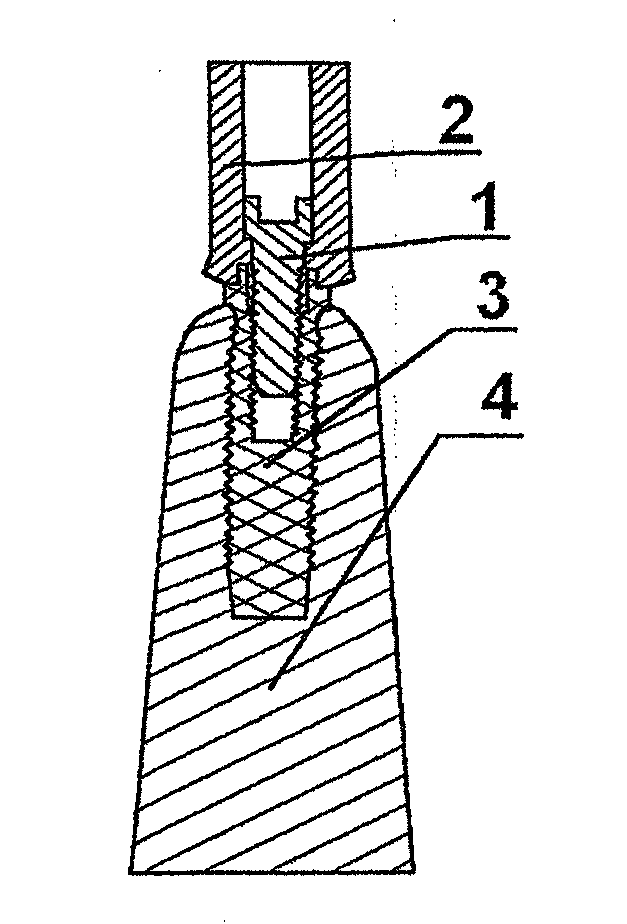
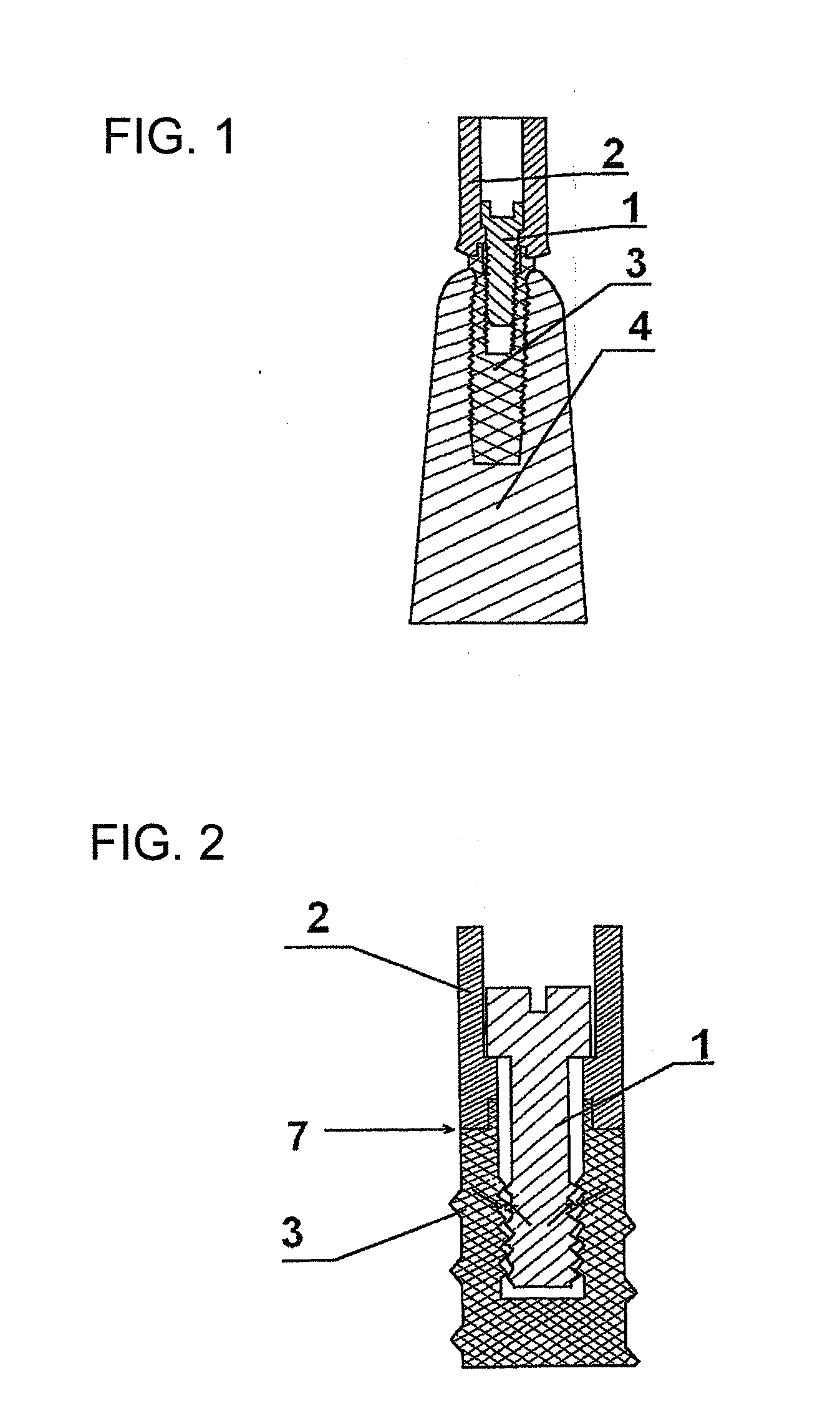
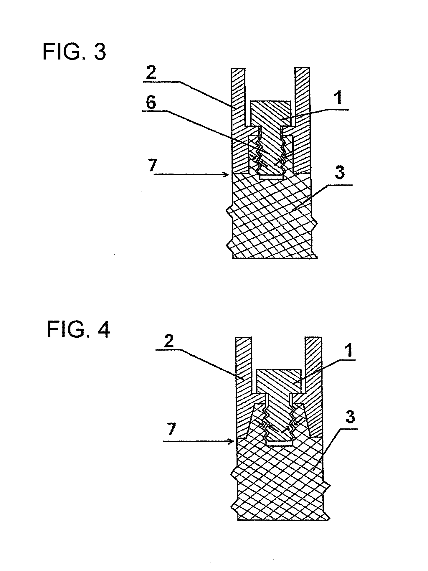
[0027]Dental prosthesis as shown in FIG. 3, FIG. 4, and FIG. 5, comprises implant 3 to be embedded into the bone tissue, said implant having bearing surface for the bottom end of abutment 2 and projection 6 with central vertical thread hole for screw 1, with the projection position on the bearing surface. Screw 1 connects implant with abutment. Abutment has receptacle hole for projection 6. Bottom end of the abutment coming in contact with the bearing surface of the implant and the lower thread of the screw connection are located above the bone tissue level 7. Optionally, on the bearing surface of the implant the groove 5 can be made with the bottom of the groove located not lower than the bone tissue level 7, and on the bottom end of the abutment corresponding projection complementary to the groove is made, as shown in FIG. 5a and FIG. 5b, to protect implant-abutment connection from the rotational forces.

[0028]Therefore, in the claimed dental prosthesis the last thread of the impla...


PUM


Abstract

A dental prosthesis has an abutment, a screw, and an implant, the bearing surface of which is embedded into bone tissue. A projection with a vertical thread hole for the screw connecting the implant with the abutment is positioned on the bearing surface of implant. The abutment has receptacle hole for the projection, and the implant supporting surface and lower thread of the screw connection are located above the bone tissue level.

Description

BACKGROUND OF THE INVENTION[0001]1. Field of the Invention[0002]The invention is related to the dentistry and is pertinent to dental prostheses having implant to be embedded into the jawbone.[0003]2. Description of the Related Art[0004]In all known dental implants the construction of implant-abutment connection is implemented either with internal extension of abutment into implant or with external extension of implant into abutment. In both types abutment and implant are connected with the screw, which passes through the center of abutment and is engaged by the threaded hole in the implant, wherein the screw of the threaded hole is positioned below the implant head level, as it is illustrated in FIG. 1. The denotations in the presented figure are as follows: screw 1 of Unigrip abutment, abutment 2, implant 3 (3.75×10-mm Mark III) and bone tissue 4. The length of the screwed in portion of the abutment screw is variable in different systems, and in some of them can reach the lower thi...

Claims


Application Information

Patent Timeline
Patent Type & Authority Applications(United States)
IPC IPC(8): A61C8/00
CPCA61C8/0006A61C8/0068A61C8/0059A61C8/005
Inventor KHRAISAT, AMEEN
Owner KHRAISAT AMEEN
Why Eureka
Try Eureka