High frequency electrical connector

a high-speed, electrical connector technology, applied in the direction of coupling device connection, two-part coupling device, electrical apparatus, etc., can solve the problems of electrical interference between adjacent signal conductors, electrical noise generation in the connector, and the general size of the electronic system, so as to reduce the resonance in pairs

Active Publication Date: 2011-09-22
AMPHENOL CORP
View PDF112 Cites 107 Cited by
  • Summary
  • Abstract
  • Description
  • Claims
  • Application Information

AI Technical Summary

Benefits of technology

[0019]An improved electrical connector is provided through the selective positioning of lossy material adjacent conductive members within the connector. In some embodiments, the lossy material is included in a broadside coupled, open pin field connector. In embodiments in which there are no conductive members specifically designed to be ground conductors, the lossy material may be placed adjacent to some conductive members that will be used to carry signals. The positioning of the lossy material relative to conductive members may be selected to reduce resonance in pairs of conductive elements if used as grounds without causing an unacceptable decrease in signal conductive elements used to carry signals.

Problems solved by technology

Electronic systems have generally become smaller, faster and functionally more complex.
One of the difficulties in making a high density, high speed connector is that electrical conductors in the connector can be so close that there can be electrical interference between adjacent signal conductors.
As signal frequencies increase, there is a greater possibility of electrical noise being generated in the connector in forms such as reflections, crosstalk and electromagnetic radiation.
For front housing portions that receive two subassemblies, lossy material between cap portions results in lossy material positioned between pairs of columns of conductive numbers.

Method used


Image

  • High frequency electrical connector
  • High frequency electrical connector
  • High frequency electrical connector

Examples


Embodiment Construction

[0048]This invention is not limited in its application to the details of construction and the arrangement of components set forth in the following description or illustrated in the drawings. The invention is capable of other embodiments and of being practiced or of being carried out in various ways. Also, the phraseology and terminology used herein is for the purpose of description and should not be regarded as limiting. The use of “including,”“comprising,”“having,”“containing,” or “involving,” and variations thereof herein, is meant to encompass the items listed thereafter and equivalents thereof as well as additional items.

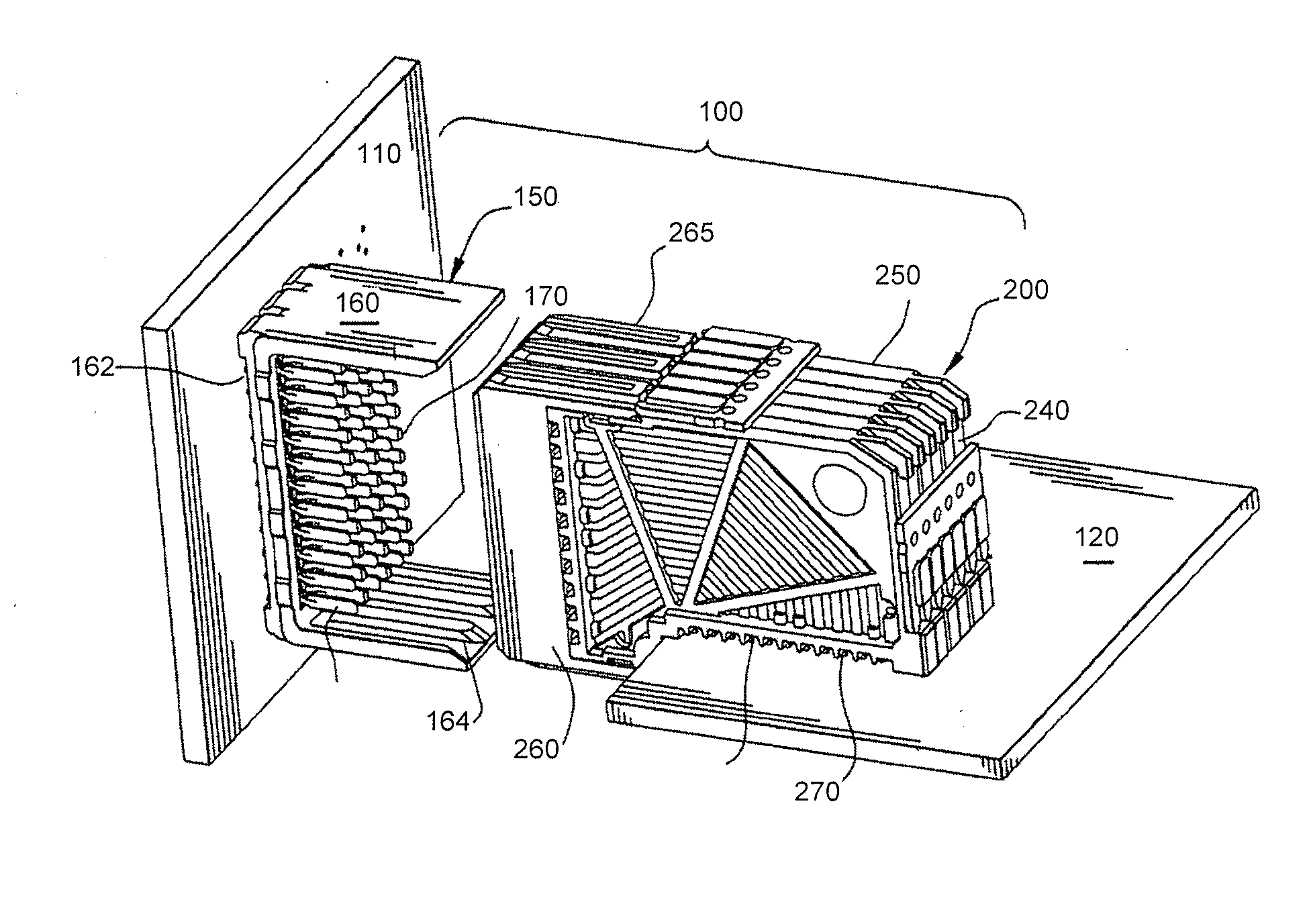
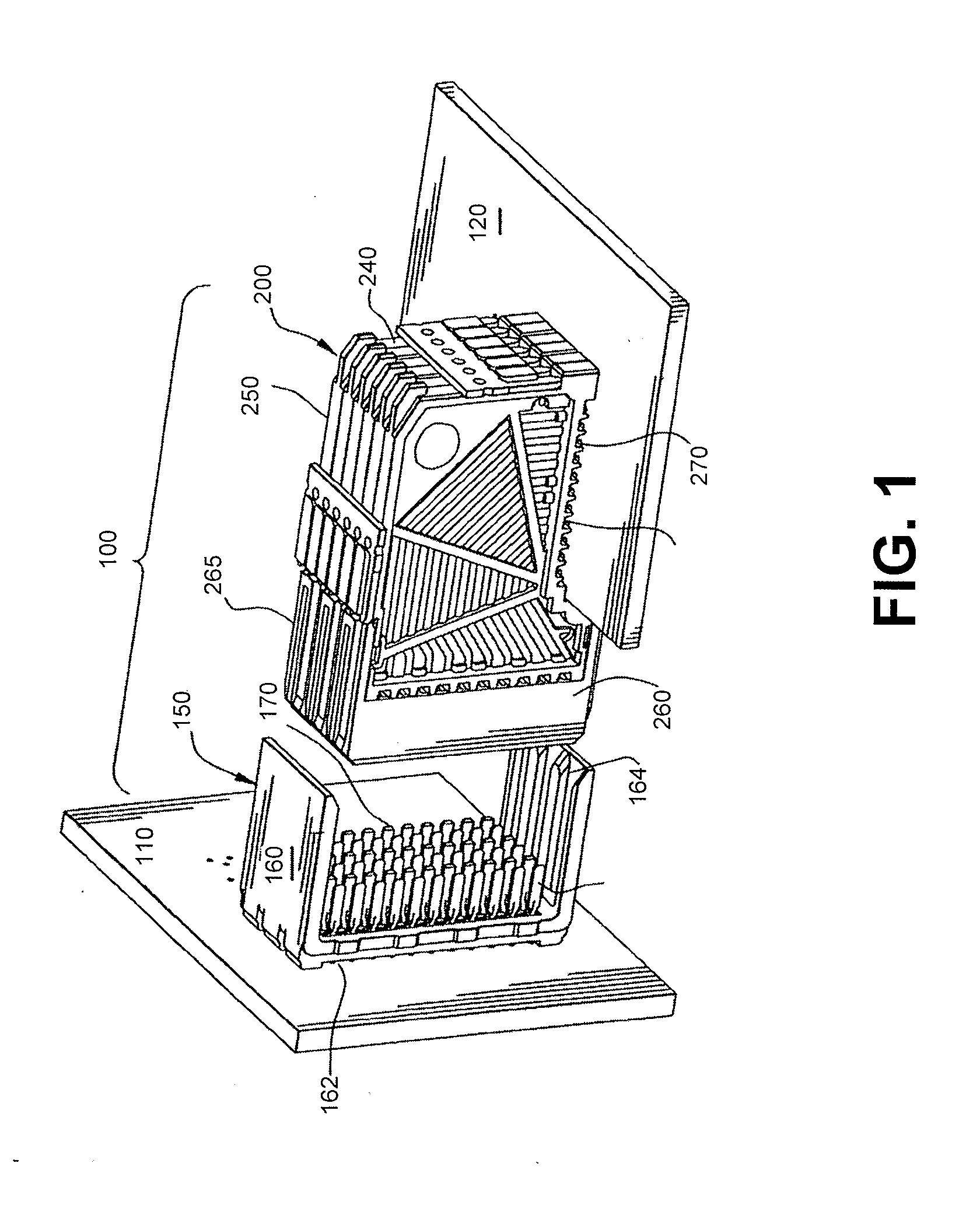
[0049]Referring to FIG. 1, a conventional electrical interconnection system 100 is shown. Interconnection system 100 is an example of an interconnector system that may be improved through the selective placement of electrically lossy material, as described below. In the example of FIG. 1, interconnection system 100 joins together PCBs 110 and 120. The electrical...


PUM


Abstract

An improved broadside coupled, open pin field connector. The connector incorporates lossy material to selectively dampen resonance within pairs of conductive members connected to ground when the connector is mounted to a printed circuit board. The material may also decrease crosstalk and mode conversion. The lossy material is selectively positioned to substantially dampen resonances along pairs that may be connected to ground without unacceptably attenuating signals carried by other pairs. The lossy material may be selectively positioned near mating contact portions of the conductive members. Multiple techniques are described for selectively positioning the lossy material, including molding, inserting lossy members into a housing or coating surfaces of the connector housing. The lossy material alternatively may be positioned between broad sides of conductive members of a pair. By using material of relatively low loss, loss when the conductive members are used to carry signals is relatively low, but an appreciable attenuation of resonances is provided on pairs connected to ground. As a result, an overall improvement of signal to noise ratio is achieved.

Description

CROSS-REFERENCE TO RELATED APPLICATIONS[0001]This application claims priority to U.S. patent application Ser. No. 11 / 476,831, filed on Jun. 29, 2006, titled “ELECTRICAL CONNECTOR FOR INTERCONNECTION ASSEMBLY”, which claims priority to U.S. Provisional Patent Application No. 60 / 695,264, filed on Jun. 30, 2005, titled “ELECTRICAL CONNECTOR WITH LOSSY MEMBERS IN CONTACT REGION,” and U.S. Provisional Patent Application No. 61 / 085,472, filed on Aug. 1, 2008, titled “HIGH FREQUENCY BROADSIDE-COUPLED ELECTRICAL CONNECTOR”, all of which are incorporated herein by reference in their entireties.BACKGROUND OF INVENTION[0002]1. Field of Invention[0003]This invention relates generally to electrical interconnection systems and more specifically to improved signal integrity in interconnection systems, particularly in high speed electrical connectors.[0004]2. Discussion of Related Art[0005]Electrical connectors are used in many electronic systems. It is generally easier and more cost effective to m...

Claims


Application Information

Patent Timeline
Patent Type & Authority Applications(United States)
IPC IPC(8): H01R13/648
CPCH01R12/585H01R13/6471H01R13/6598H01R24/62H01R12/724H01R12/735H01R13/658H01R13/514H01R13/6477H01R13/6585H01R13/6587H01R24/68H01R13/504H01R13/6461
Inventor ATKINSON, PRESCOTT B.KIRK, BRIANGAILUS, MARK W.MANTER, DAVIDCOHEN, THOMAS S.
Owner AMPHENOL CORP
Why Eureka
Try Eureka