
Ventilation valve for a veterinary anesthesia system

a technology of ventilator and anesthesia system, which is applied in the field of veterinary medical devices, can solve the problems of user forgetting to move the valve back, the rebreathing circuit is often not used, and the patient's breathing is often assisted

Active Publication Date: 2011-09-29
LATSHAW HARRY
View PDF10 Cites 2 Cited by
  • Summary
  • Abstract
  • Description
  • Claims
  • Application Information

AI Technical Summary

Benefits of technology

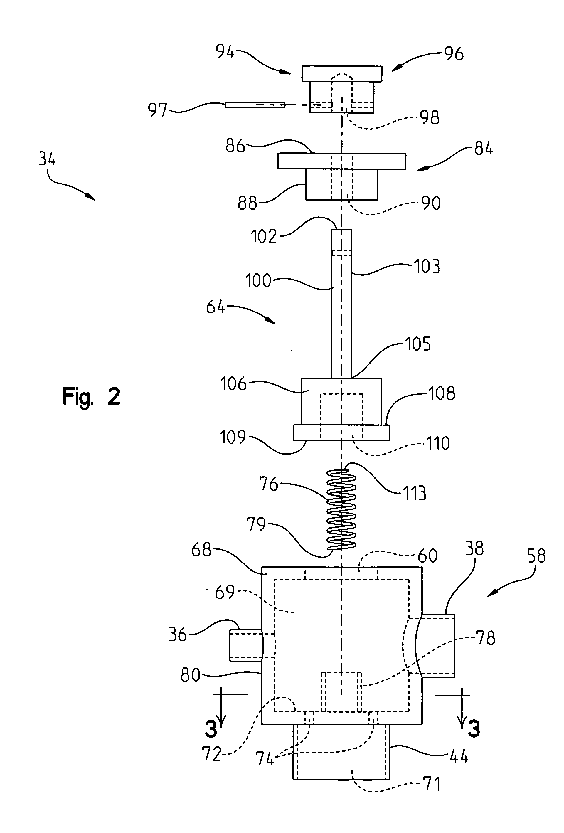
[0022]In accordance with the present invention, a valve is provided for controlling the flow of gas through an anesthesia or breathing circuit. The valve comprises a valve body having a first port, a second port, and a third port. The third port includes a flow restrictor for restricting the flow of gas through the third port. A valve closing member is provided that is moveable between an open position where gas can flow through the third port, and a closed position. In the closed position, gas is prevented from flowing through the third port.
[0023]In a preferred embodiment of the present invention, the flow restrictor can include a plurality of apertures having a collective area smaller than the collective area of the third port. The plurality of apertures are preferably sized to permit gas to flow, under normal conditions, when the valve is open, from the first port into each of the second and third ports. The collective area of the plurality of apertures should be sized to be large enough, when the valve is in the open position, to prevent air in the breathing bag from exerting enough back pressure through the first port to impede breathing of a patient coupled to the first port and valve.

Problems solved by technology

However, with smaller animals, a rebreathing circuit is often not used.
One problem that exists when performing anesthesia procedures on animal patients, is that animal patients often need to have their breathing assisted.
One problem with the valve and the fitting, is that currently known valves and fittings typically have an “on” position and an “off” position, and can rest in and remain statically positioned in each of the “on” and “off” positions.
Unfortunately, during the passage of time during procedures, users often forget to move the valve back into the open position.
The failure to move the valve back into the open position can have deleterious effects on the animal.
Another problem that exists with conventional fittings is that many require that the valve be closed for a certain period of time, in order to inflate the vent bag.

Method used


Image

  • Ventilation valve for a veterinary anesthesia system
  • Ventilation valve for a veterinary anesthesia system
  • Ventilation valve for a veterinary anesthesia system

Examples


Embodiment Construction

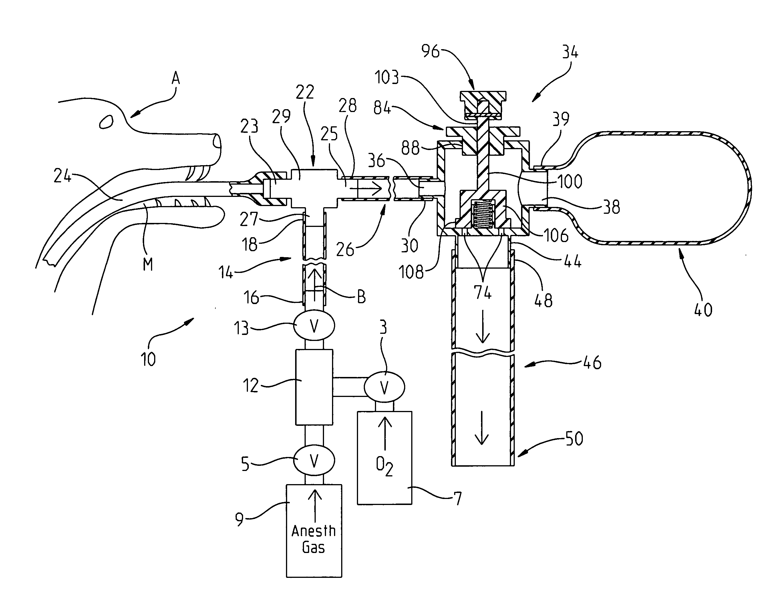
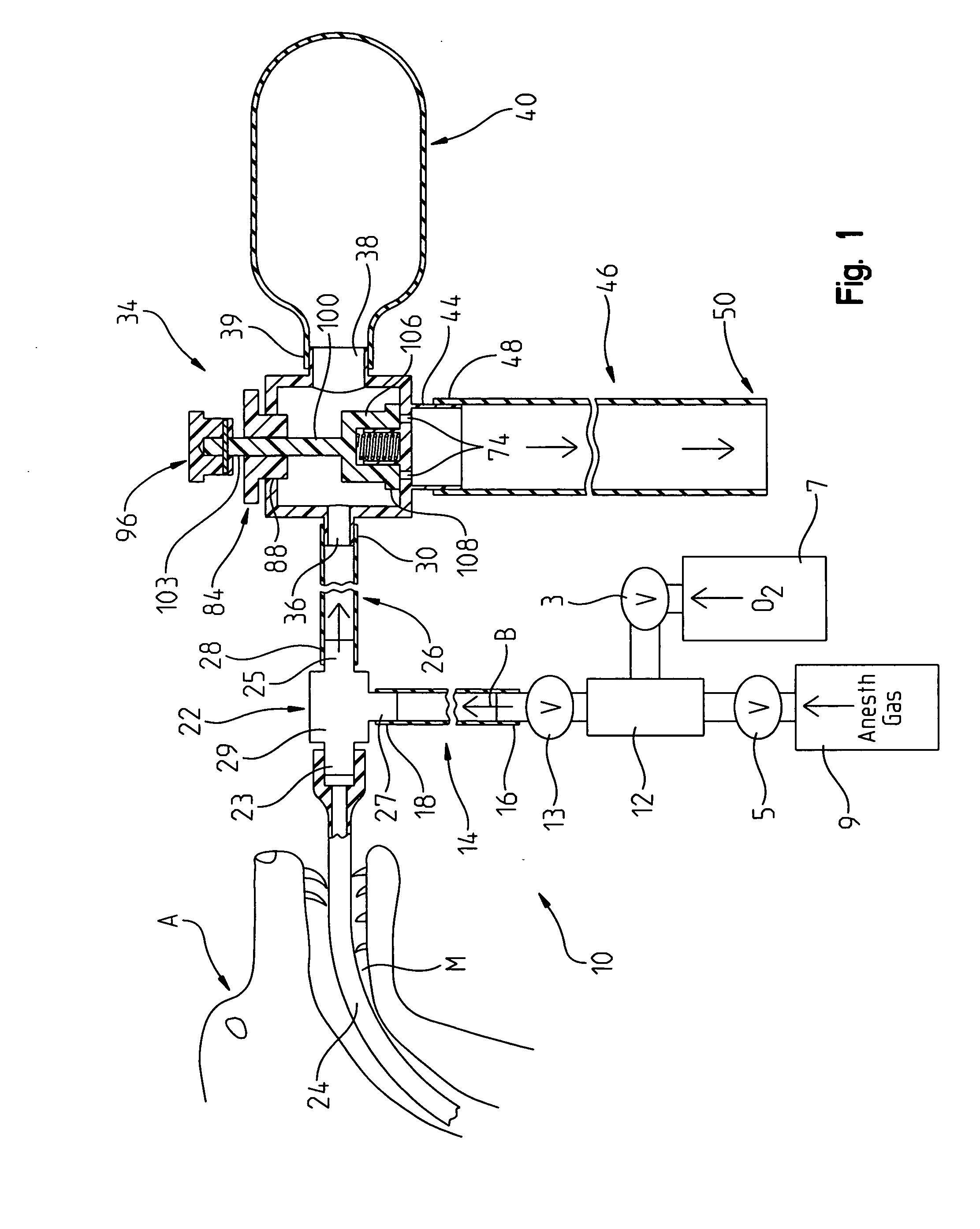
[0031]Turning now to FIG. 1, an anesthesia system breathing circuit 10 is shown that is used in connection with an animal A. Those familiar with breathing circuits will recognize that the breathing circuit 10 has some similarities to a Mapleson type of breathing circuit.

[0032]The breathing circuit 10 is coupled to a gas source 12. Preferably, the gas source includes both a source of anesthesia gas 9, along with a source of oxygen 7. In such a Mapleson type circuit, the patient is usually fed a gas and oxygen mixture. Valves 3,5 are positioned for controlling the flow of oxygen and gas into the source 12. A valve 13 is coupled to the gas source 12 to control the flow of gas from the gas source 12 to an inspiratory tube 14. As used herein, the term “gas” will refer generally to an appropriate mixture of anesthesia gas, air, and / or oxygen (and possibly other gases), it being appreciated the percentage mixture of materials is subject to wide variation, depending upon the procedure, the ...


PUM


Abstract

A valve is provided for controlling the flow of gas through an anesthesia or respiratory breathing circuit. The valve includes a valve body having a first port, a second port, and a third port. The third port includes a flow restrictor for restricting the flow of gas through the third port. A valve closing member is provided that is moveable between an open position where gas can flow through the third port, and a closed position. In the closed position, gas is prevented from flowing through the third port.

Description

I. REFERENCE TO RELATED PATENT APPLICATION[0001]This U.S. Non Provisional patent application claims the benefit of and / or priority to Latshaw, U.S. provisional patent application Ser. No. 61 / 340,930 filed Mar. 24, 2011 entitled “Ventilation Valve for a Veterinary Anesthesia System”, the entire content of which is specifically incorporated herein by reference.II. TECHNICAL FIELD OF THE INVENTION[0002]The present invention relates to veterinary medical devices, and more particularly to a valve useable with an anesthesia system for veterinary purposes, and the anesthesia system including such a valve.III. BACKGROUND OF THE INVENTION[0003]Anesthesia systems have long been in use on both animals and human beings in order to sedate the patient prior to surgical operations. The administration of anesthetics during surgery reduces or eliminates and provides the physician with a more cooperative patient. The anesthesia art is probably more highly developed with human beings, as humans have b...

Claims


Application Information

Patent Timeline
IPC IPC(8): A61D7/04
CPCA61D7/04
Inventor LATSHAW, HARRY
Owner LATSHAW HARRY
Learn More