Method for processing froth treatment tailings

a technology of froth treatment and tailings, which is applied in the direction of liquid hydrocarbon mixture production, petroleum industry, solid separation, etc., can solve the problem that the significant amount of bitumen from the original oil sand ore is therefore typically lost to the froth treatment tailings, and achieves the effect of enhancing the recovery of the amount of diluen

Active Publication Date: 2011-09-29
TITANIUM CORP
View PDF11 Cites 11 Cited by
  • Summary
  • Abstract
  • Description
  • Claims
  • Application Information

AI Technical Summary

Benefits of technology

This patent describes how to make a concentrated mixture of different minerals that can be used to extract a liquid substance called a diluent. By controlling the ratio of solids to liquids in this mix, researchers found they could improve the efficiency of getting the diluent out of it. Specifically, they discovered that if the concentration of solid materials was between 60% and 84%, they could achieve better results than other ratios. Additionally, adding more water to the mix also improved the process. Overall, these findings provide technical details on optimizing the extraction of diluents from mineral mixtures.

Problems solved by technology

The technical problem addressed in this patent text relates to finding ways to improve the efficiency of removing bitumen from foam treatment tailings while reducing the loss of valuable heavy minerals. Previous methods have either focused on making sure the bitumen content meets certain requirements or trying to recycle the remaining bitumen through various means. However, none of the previous methods appear to focus specifically on creating a debitumzed heavy mineral concentrate and a bitumen extract from the froth treatment tailings.

Method used


Image

  • Method for processing froth treatment tailings
  • Method for processing froth treatment tailings
  • Method for processing froth treatment tailings

Examples


example 1

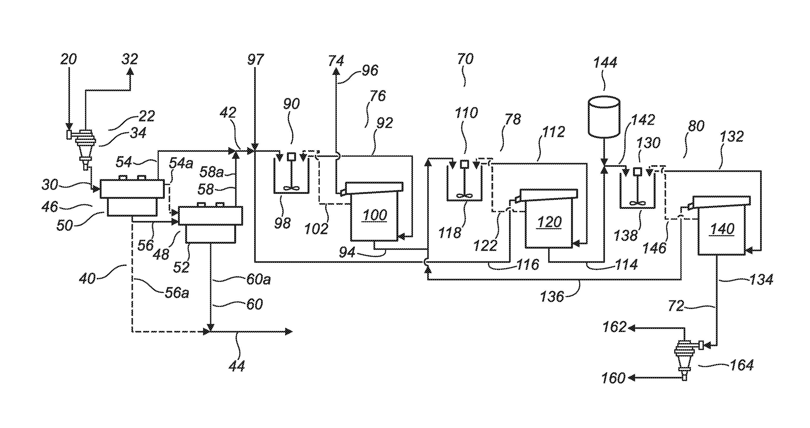
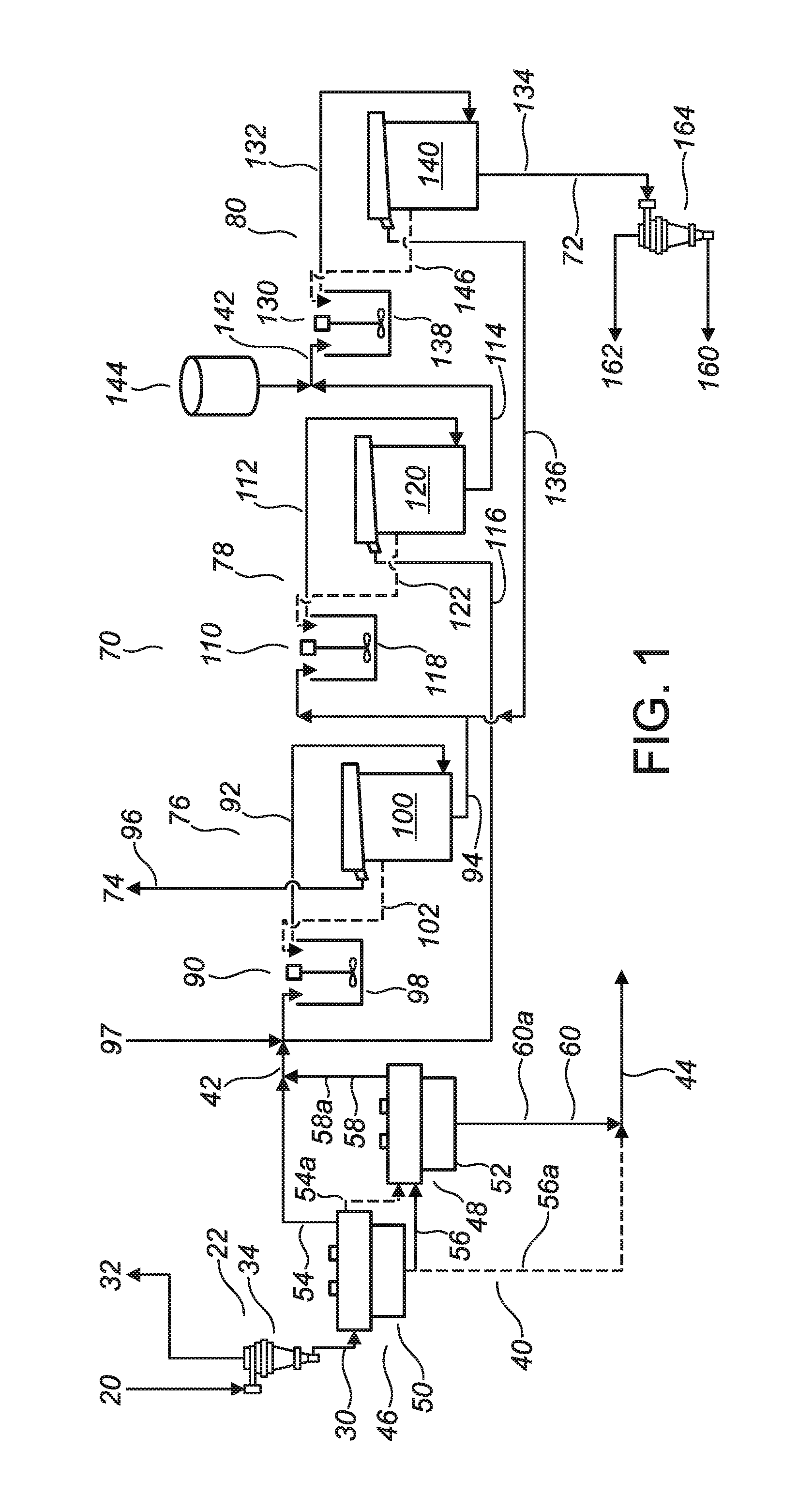
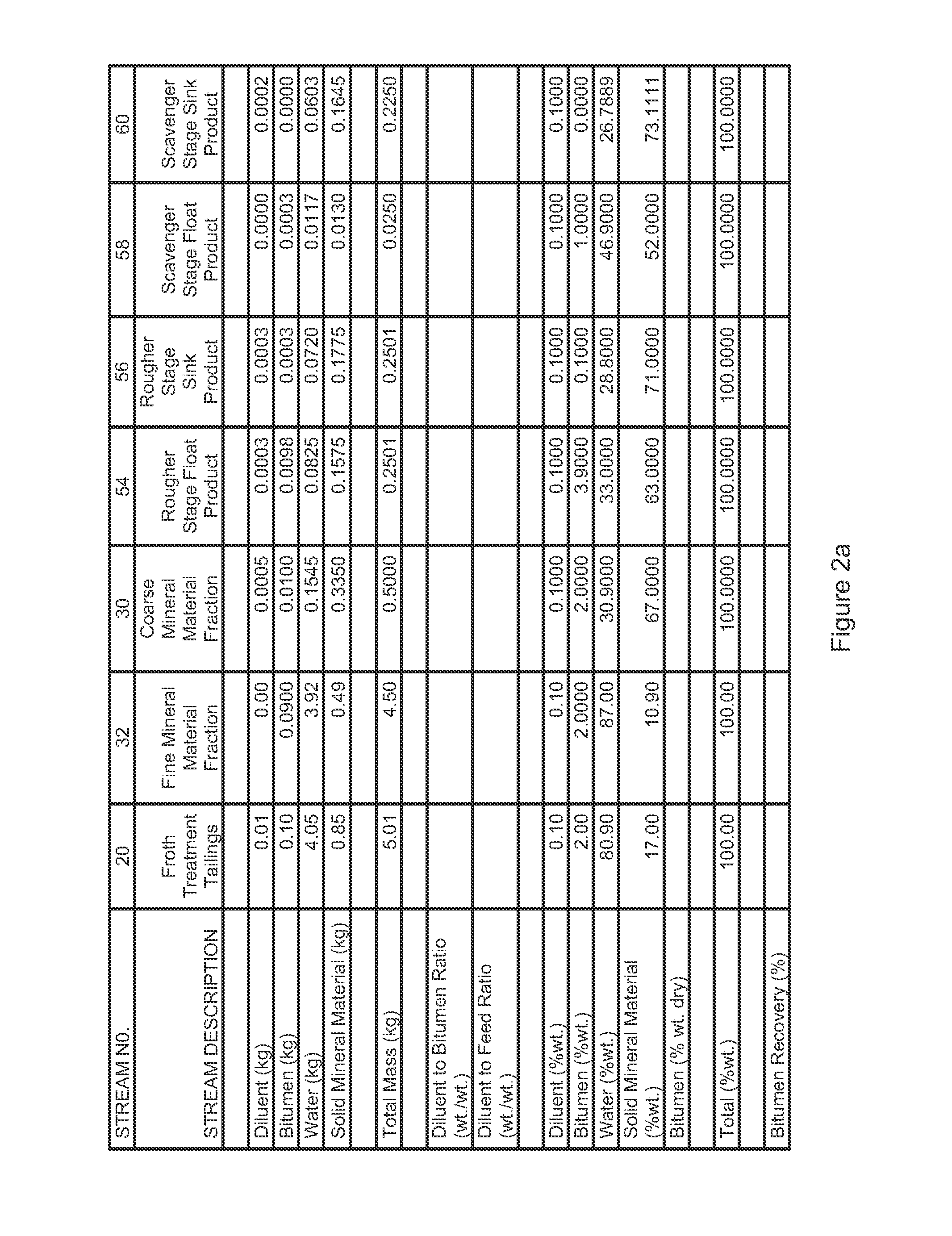
[0202]Referring to FIG. 2, a material balance is provided for a bench scale test simulating the embodiment of the invention depicted by the solid lines in FIG. 1. The material balance of FIG. 2 does not include a simulation of the alternate or optional features which are depicted by the dashed lines in FIG. 1. Consequently, in the material balance of FIG. 2, the froth flotation (40) is arranged in a scavenging configuration, and the solvent extraction (70) does not include recycling of the solvent extraction intermediate components (102,122,146).

[0203]In the bench scale test which is represented by FIG. 2, the solvent extraction (70) was performed by adding “fresh” naphtha as a hydrocarbon diluent in each of the three solvent extraction stages (76,78,80) instead of by recycling the overflow components (116,136) from the second and third solvent extraction stages (78,80) respectively. The overflow components (116,136) were, however, taken into consideration in calculating the materia...

example 2

[0211]Referring to FIG. 3, a material balance is provided for a heavy mineral concentrate produced by a bench scale test simulating a froth flotation (40) performed according to the embodiment of FIG. 1, including a rougher froth flotation stage and a scavenger froth flotation stage.

[0212]Referring to FIG. 3, it is noted that about 97.5 percent of the total heavy minerals contained in the coarse mineral material fraction (30) were recovered in the heavy mineral concentrate (42), about 81.6 percent of the hydrocarbons contained in the coarse mineral material fraction (30) were recovered in the heavy mineral concentrate (42), about 97.5 percent of the TiO2 values contained in the coarse mineral material fraction (30) were recovered in the heavy mineral concentrate (42), and about 99.1 percent of the ZrO2 values contained in the coarse mineral material fraction were recovered in the heavy mineral concentrate (42).

example 3

[0213]Referring to FIG. 4, a graph is provided of data obtained from bench scale tests of one stage, two stage, and three stage solvent extractions (70) performed according to the invention a different diluent amounts in the feed material, depicting bitumen concentration of a debitumenized heavy mineral concentrate (72) by dry weight of the debitumenized heavy mineral concentrate (72) as a function of diluent amount and as a function of the number of solvent extraction stages.

[0214]Referring to FIG. 4, it is noted that a bitumen concentration of less than about 0.5 percent by dry weight of the debitumenized heavy mineral concentrate (72) was achieved by a three stage solvent extraction in which the diluent amount was at least 15 percent by weight of the feed material.


PUM


Abstract

A method for processing froth treatment tailings, including separating the froth treatment tailings in order to produce a coarse mineral material fraction and a fine mineral material fraction therefrom, subjecting the coarse mineral material fraction to froth flotation in order to produce a heavy mineral concentrate and a coarse mineral material tailings therefrom, and subjecting the heavy mineral concentrate to solvent extraction in order to produce a debitumenized heavy mineral concentrate and a bitumen extract therefrom.

Description


Claims


Application Information

Patent Timeline
Owner TITANIUM CORP
Why Eureka
Try Eureka