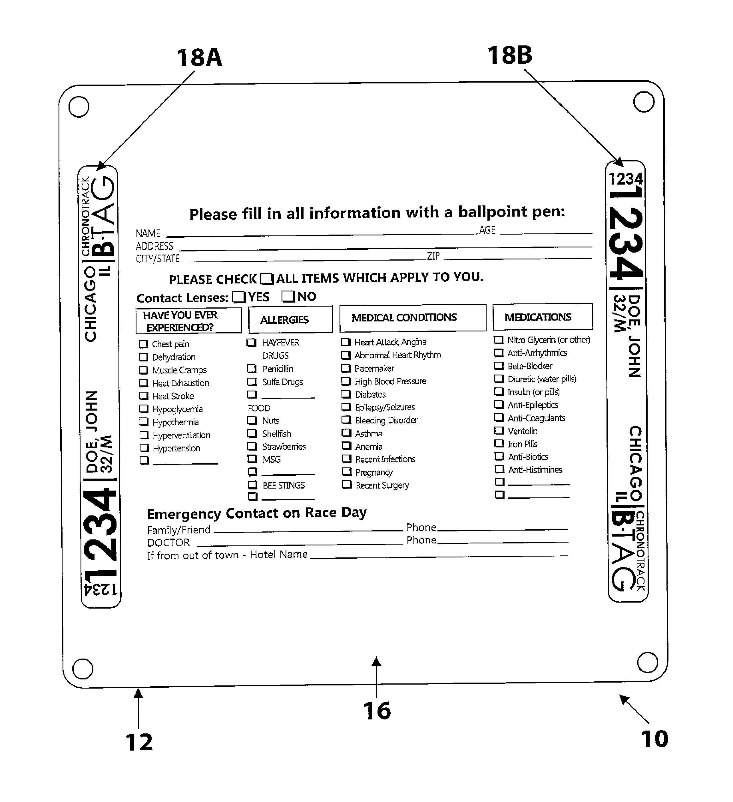
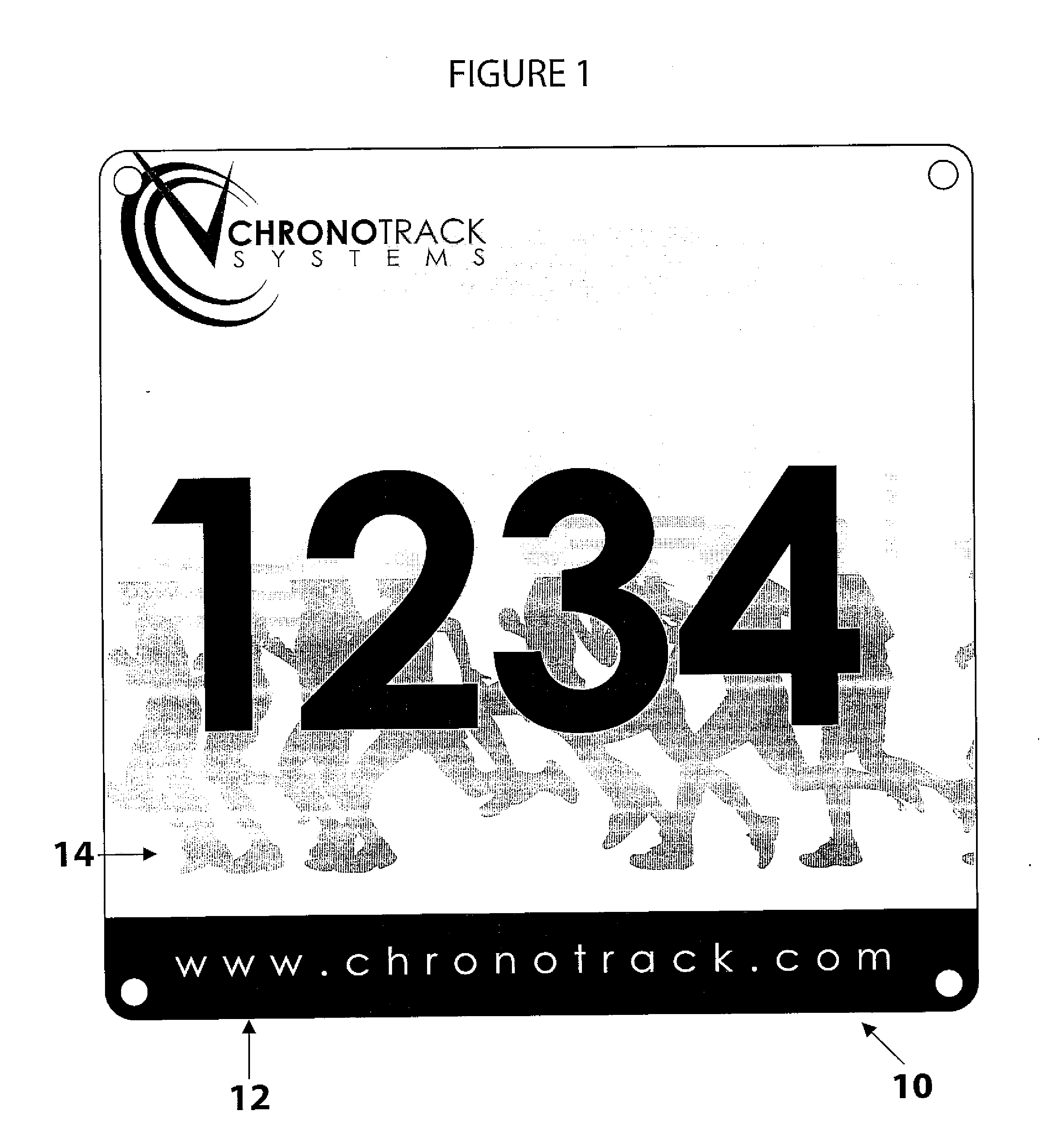
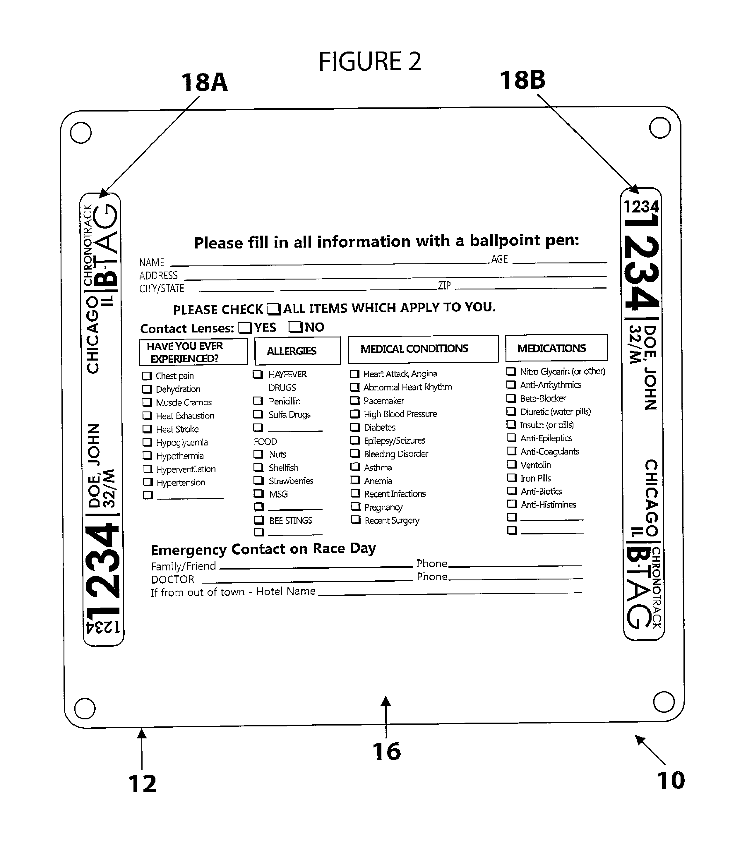
[0018]FIGS. 1-3 illustrate an improved race bib timing device 10 according to a presently preferred embodiment of the present invention. According to the presently preferred embodiment, the improved race bib timing device includes a race bib 12, having a front surface 14 and a rear surface 16. The race bib 12 is preferably formed of a planar, paper-like material that can be removably affixed to the shirt, shorts or other garment of a participant in an event such as a marathon, road race, track and field event, cross country race, skiing event, biking event, triathalon, or other sporting event where participants are assigned a number for timing and/or ranking purposes. In many instances, the race bib 12 is formed of a water proof and tear resistant material, such as TYVEK. The front surface 14 of the race bib 12 can be used to display data and information, including, but not limited to the participant's assigned entry or race number, the name of the race, or other desired information. The rear surface 16 of the race bib 12 is typically devoid of any such information as it is commonly placed against the outer surface of the participant's garment when in use.
[0019]According to the present invention, two or more timing tags 18a, 18b are associated with the race bib 12 for obtaining timing information about the participant when used in conjunction with a race timing system and readers. As shown in FIG. 2, according to one embodiment of the present invention, two timing tags 18a, 18b are positioned on the rear surface 16 of the race bib 12. It is also contemplated that the timing tags could be located on the front surface 14 of the race bib 12, or embedded within the race bib itself, or that more than two timing tags could be utilized. As shown in FIG. 2, the two or more timing tags 18a, 18b are positioned parallel to one another such that the antennae therein are linearly polarized relative to one another. The two or more timing tags 18a, 18b are also positioned on the race bib 12 such that, when the bib is affixed to the garment of the participant, the timing tags 18a, 18b are oriented such that they are perpendicular to the tag reader. For example, where reader antennae are employed in a ground-based antenna reader system such as is described in applicant's corresponding provisional patent application Ser. No. 61/182,520, the timing tags 18a, 18b should be oriented such that, when applied to the garment of the participant, they are oriented vertically relative to the ground and the antenna reader.
[0020]As best shown in FIG. 3, each timing tag 18 is a preferably planar member 20, preferably having a substantially rectangular cross-section, and is preferably formed of a flexible, water resistant sheet type material having very low conductivity, such as sheet plastic or laminated paper. An integrated circuit 26 and antenna 28 are formed on the planar member 20 of the timing tag 18. The integrated circuit 26 and antenna 28 are preferably formed on the rear surface of the timing tag 18 to protect those components from the elements. It is also contemplated that the integrated circuit 26 and/or antenna 28 be formed on the front surface of the planar member 20 of the timing tag 18. The integrated circuit 26 is used for storing and processing information, modulating and demodulating a radio-frequency (RF) signal and other specialized functions. The integrated circuit 26 includes memory circuits and logic circuits. The logic circuits store, retrieve, and manipulate data that is encoded into the memory circuits. The logic circuits of the integrated circuit 26 receive and transmit data externally from the timing tag 18 via RF signals. The timing tag is preferably a passive RFID tag, which has no battery and requires an external source to provoke signal transmission. Alternatively, the timing tag 18 could be an active RFID tag, which contains a battery and can transmit signals autonomously.
[0021]The antenna 28 is electrically connected to the integrated circuit 26 and is configured for receiving and transmitting the signal. The antenna 28 picks up signals from an RFID reader or scanner and then returns the signal, with some additional data—in this case, the runner's bib number and related information that has previously been encoded on the memory circuits of the integrated circuit 26. The antenna 28 is a conductive element that permits the timing tag 18 to exchange data with a remote reader. The antenna array is large relative to the surface of the timing tag to permit the data to be read at a distance from the transmitting antenna.
[0022]Passive RFID tags, such as are contemplated in the preferred embodiment of the present invention, make use of a coiled antenna that can create a magnetic field using the energy provided by the reader's carrier signal. A passive tag does not contain a battery; the power is supplied by the reader. When radio waves from the reader are encountered by a passive RFID tag, the coiled antenna within the tag forms a magnetic field. The tag draws power from it, energizing the circuits in the tag. The tag then sends the information encoded in the tag's memory to the reader.
[0023]The integrated circuit 26 and antenna 28 comprise a singular structure with a printed RFID circuit, thereby minimizing its profile and weight. According to one preferred embodiment of the invention, a DogBone RFID tag manufactured by UPM Raflatac is utilized. The integrated circuit used is EPC Class 1 Gen 2 compliant and 96 bit EPC memory is provided. The integrated circuit operates at a frequency of 860-960 MHz. The antenna measures approximately 93×23 mm. Other antenna configurations and integrated circuits may be used in keeping with the spirit of the invention.
[0024]It has been discovered through testing that the RFID tag does not operate to its potential when the integrated circuit and antenna are allowed to come in contact with moisture and heat that may be present on the surface of the participant's garment. Thus, in order for the RFID tag to operate properly, in use as a timing tag, it is necessary to insure that moisture and heat from the participant do not interfere with the integrated circuit 26 and antenna 28. This is accomplished by providing a protective layer or coating 30 between the timing tag 18 and the participant. According to one presently preferred embodiment, the protective layer or coating 30 is a product known as RFIDefend produced by MPI Label Systems. The RFIDefend has a unique and proprietary material construction that provides added protection to the inlay in applications where the RFID tag is subjected to impact, abrasion, heat or moisture. It also allows the entire label to be printed without quality interference from the chip and withstands exposure to outdoor elements. Although only a single protective layer or coating 30 is shown in FIG. 3, it is contemplated to provide multiple layers and/or coatings and/or coatings of varying thicknesses to achieve the desired isolation of the RFID tag from heat and moisture from the athlete.
[0025]The foregoing is provided for purposes of illustrating, explaining, and describing embodiments of the present invention. The specific components and order of the steps listed above, while preferred is not necessarily required. Further modifications and adaptation to these embodiments will be apparent to those skilled in the art and may be made without departing from the scope or spirit of the invention.