Power generation system and sensing system

a power generation system and sensing technology, applied in the direction of power supply testing, moving-iron instruments, instruments, etc., can solve the problems of expensive installation of wind mills or vibrating boards, many problems in the foregoing power generation systems,

Inactive Publication Date: 2011-09-29
EMPIRE TECH DEV LLC
View PDF11 Cites 12 Cited by
  • Summary
  • Abstract
  • Description
  • Claims
  • Application Information

AI Technical Summary

Problems solved by technology

However, the foregoing power generation systems using wind mills or vibrating boards have

Method used


Image

  • Power generation system and sensing system
  • Power generation system and sensing system
  • Power generation system and sensing system

Examples


first example embodiment

I. First Example Embodiment

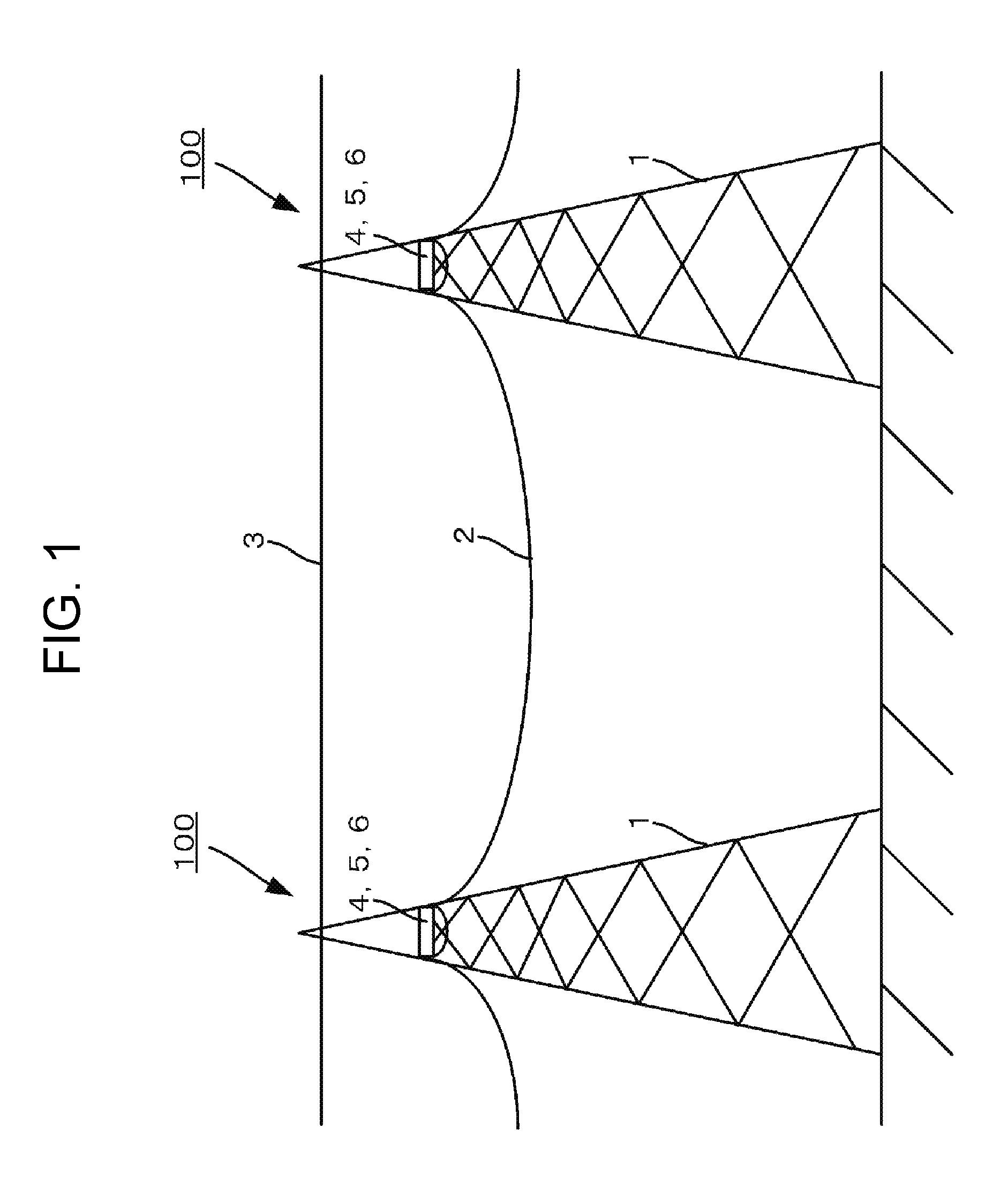
[0022]FIG. 1 is a view illustrating an example power generation system 100 using a power transmission line.

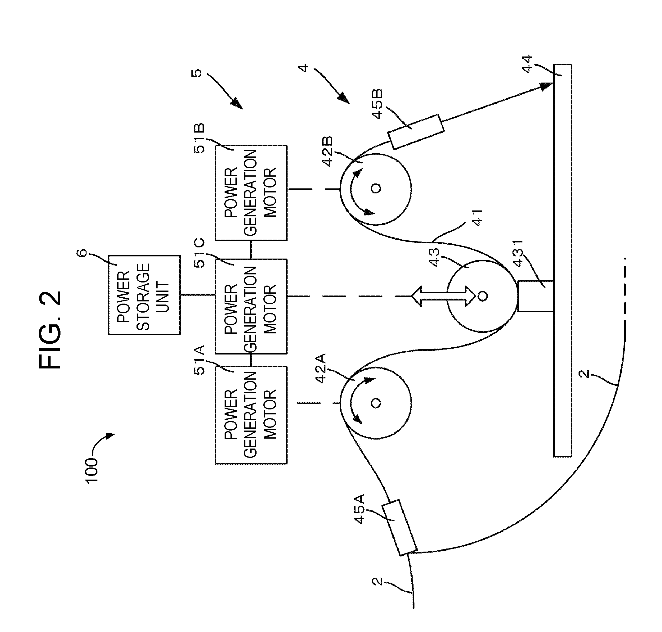
[0023]As illustrated in FIG. 1, the power generation system 100 includes a transmission line tower 1, a power transmission line 2, an overhead ground wire 3, a support unit 4, a power generation unit 5 and a power storage unit 6.

[0024]The transmission line tower 1 may include a structure made of iron frames or other suitable material. The transmission line tower 1 is a tower on which the power transmission line 2 is suspended and supported.

[0025]The power transmission line 2 is an electric line used to transmit electric power generated by a power generation plant to a power distribution grid. The power transmission line 2 is disposed between the power generation plant and a transformer station and between the transformer station and another transformer station.

[0026]The overhead ground wire (GW) 3 is a metal wire used to protect the power transmission...

second example embodiment

II. Second Example Embodiment

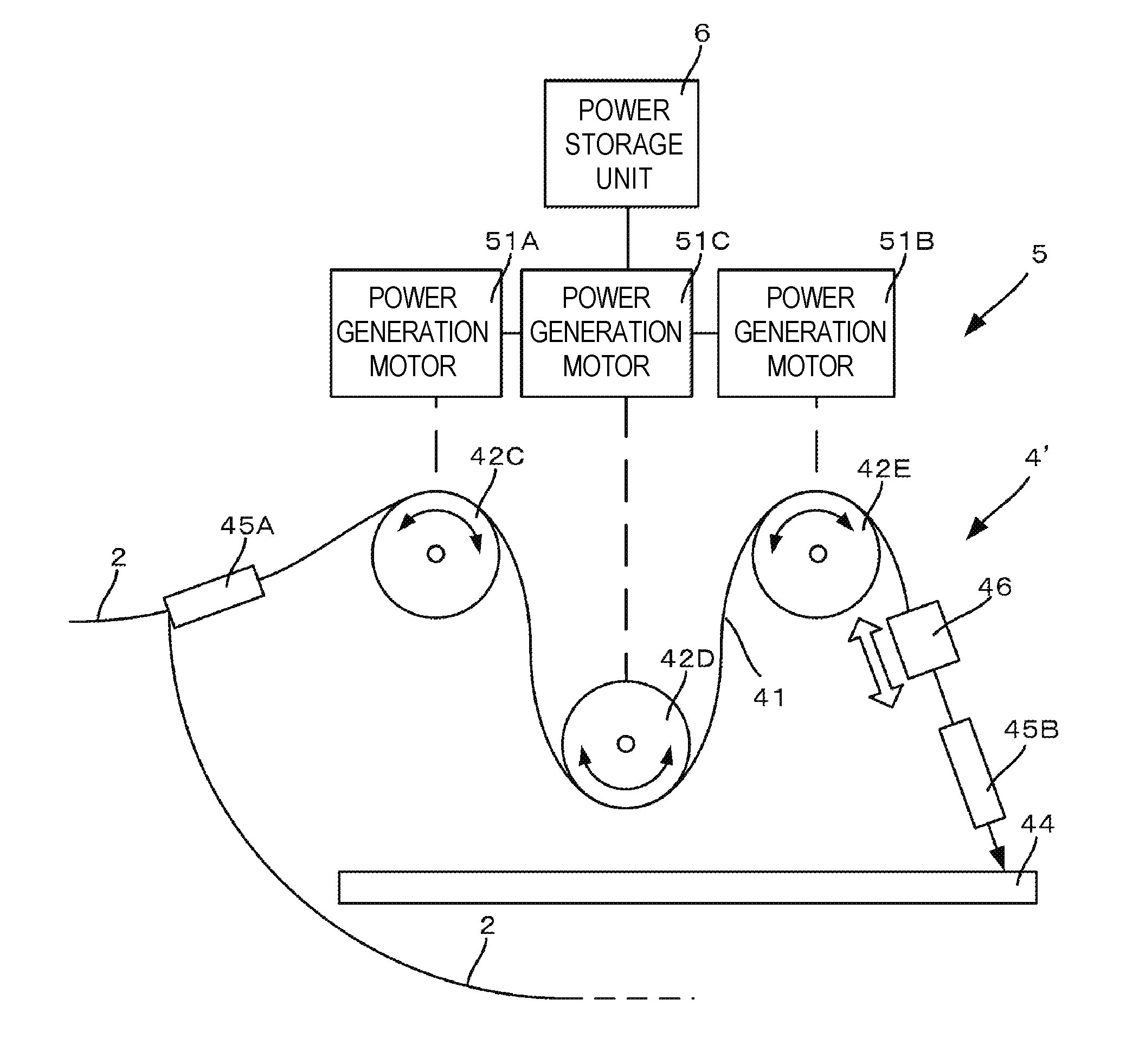
[0044]FIG. 4 is a schematic configuration diagram of a power generation system 200 according to some embodiments. In the power generation system 200 of FIG. 4, some power generation elements are added to the constituent elements of the power generation system 100 described with respect to FIGS. 1-3. In the following description, an explanation is omitted for constituent elements of the power generation system 200 that are similar to those of the power generation system 100.

[0045]As illustrated, the power generation system 200 includes a support unit 4, a power generation unit 5′, and a power storage unit 6. The power generation unit 5′ includes a connection unit 52 and a piezoelectric element 53 configured to be deformed (for example, pressed) by movement of the connection unit 52 so as to generate electric power.

[0046]The connection unit 52 is a member, disposed in the support line 41, configured to move in response to relative movement of the support l...


PUM


Abstract

A power generation system includes a support unit configured to support a power transmission line disposed on a transmission line tower, and a power generation unit. The support unit includes a support line having an end part connected to the power transmission line and a rotary body configured to rotate in a manner cooperating with the support line. The power generation unit is configured to generate electric power in response to rotation of the rotary body caused by movement of the support line resulting from tension of the power transmission line.

Description

CROSS-REFERENCE TO RELATED APPLICATIONS[0001]This application claims priority to Japanese Patent Application No. 2010-075351 filed Mar. 29, 2010, which is incorporated herein by reference in its entirety.TECHNICAL FIELD[0002]Embodiments disclosed herein relate to a power generation system and a sensing system.BACKGROUND[0003]As a countermeasure against global warming, power generation systems using natural energy such as wind power are attracting great attention.[0004]Some power generation systems using wind power include a wind mill rotated by wind such that a torque of the wind mill drives a power generation motor to generate electric power. Other power generation systems using wind power include a piezoelectric element attached to a board vibrated by wind such that vibrations of the board deform the piezoelectric element to generate electric power. See “Wind power generation, Introduction for beginners”, [online], [Search: Mar. 25, 2010], <URL: http: / / windhp.seesaa.net / article...

Claims


Application Information

Patent Timeline
IPC IPC(8): G01R31/40G01R19/00H02K7/18
CPCY02E10/70F03G7/08
Inventor FUSE, KENICHI
Owner EMPIRE TECH DEV LLC
Why Eureka
Try Eureka