Display input device

a display input and input device technology, applied in surveying and navigation, navigation instruments, instruments, etc., can solve the problems of reducing the ease of use of the display input device, affecting the accuracy of the output, and the scale of enlargement is fixed, so as to facilitate the input operation of the user and improve the ease of us

Active Publication Date: 2011-09-29
AUTO TECH GRP LLC
View PDF23 Cites 61 Cited by
  • Summary
  • Abstract
  • Description
  • Claims
  • Application Information

AI Technical Summary

Benefits of technology

[0012]Therefore, the display input device in accordance with the present invention makes it easy for a user to perform an input operation even when a vibration is occurring, and provides excellent ease of use.

Problems solved by technology

However, when a user operates the display input device while standing or in a case in which the display input device is applied to vehicle-mounted information equipment, it is undeniable that the ease of use of the display input device is reduced as the screen vibrates because the user's finger vibrates or the vehicle is running.
Furthermore, according to the technology disclosed by patent reference 2, if the position of the finger is too far away from the touch panel face when trying to control the scaling, the scaling sways due to a vibration in the Z axial direction of the finger, and therefore the control operation may become difficult.
In addition, a problem with the technology disclosed by patent reference 3 is that the scale of enlargement is fixed and therefore any user's intention is not reflected.

Method used


Image

  • Display input device
  • Display input device
  • Display input device

Examples


embodiment 2

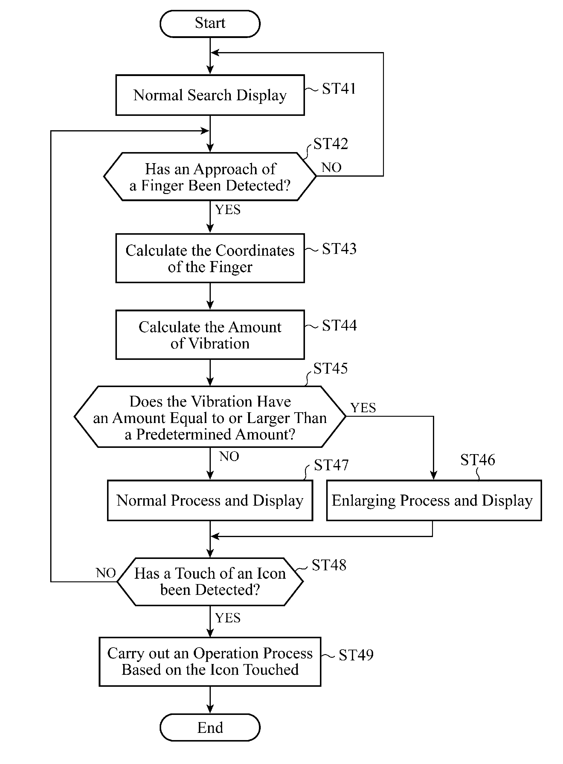
[0072]FIG. 8 is a flowchart showing the operation of a display input device in accordance with Embodiment 2 of the present invention. In Embodiment 2 which will be explained hereafter, an example in which the display input device explained in Embodiment 1 is applied to a vehicle so as to enlarge an image in a display area having a fixed range to a further larger size to display the further-enlarged image while the vehicle is running, thereby, even if the vehicle is running, making it easy for a user to perform an input operation, and providing a further improvement in the ease of use of the display input device will be shown.

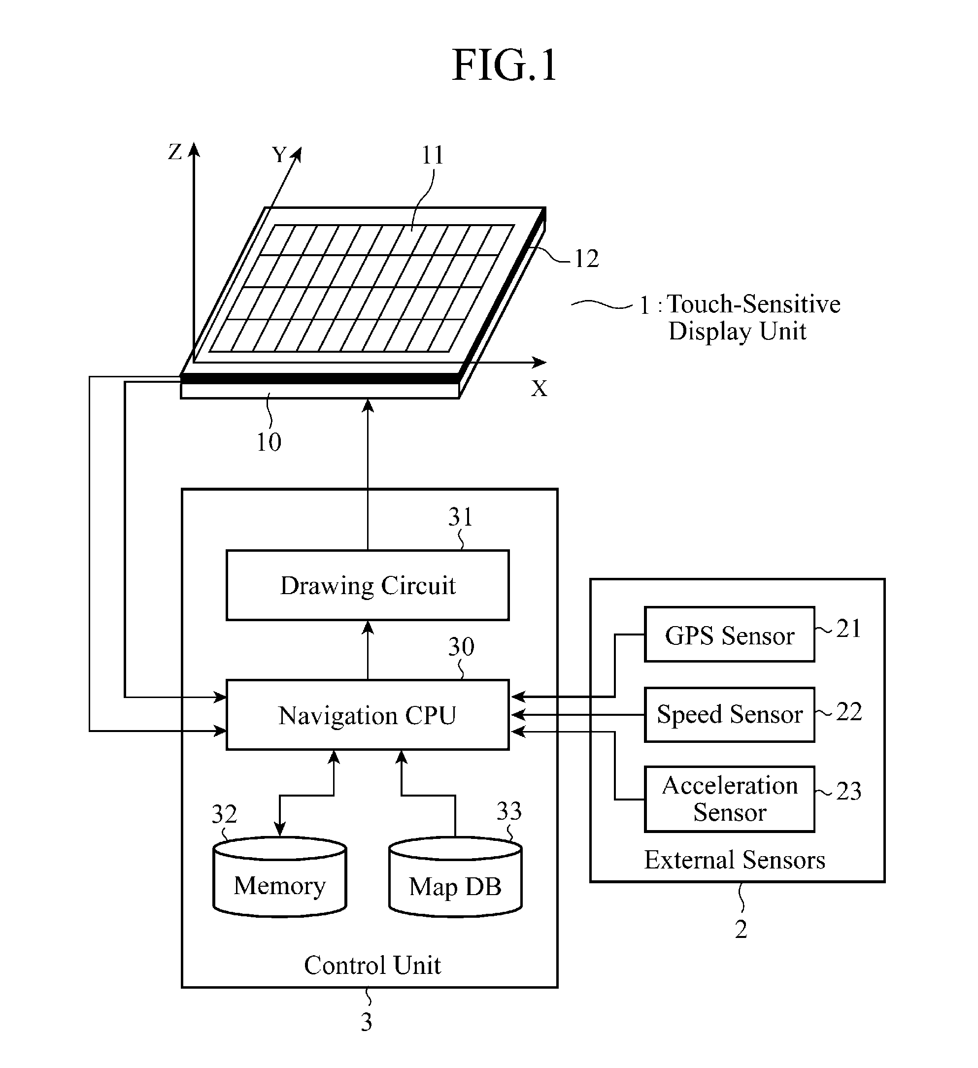
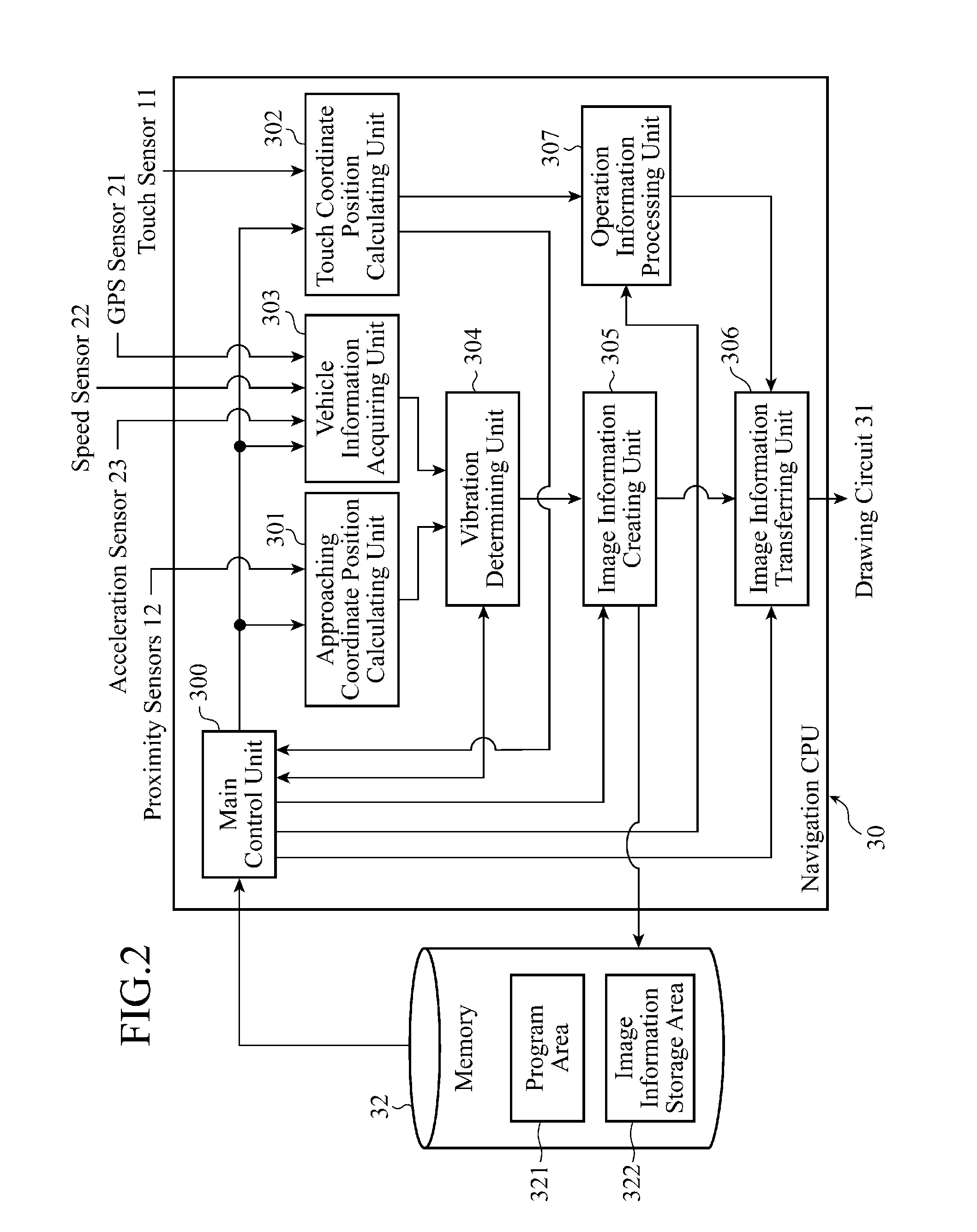
[0073]Also in Embodiment 2 which will be explained hereafter, the display input device can employ the same structure as that shown in FIGS. 1 to 3, like that in accordance with above-mentioned Embodiment 1.

[0074]In the flow chart of FIG. 8, a soft keyboard used at the time of a facility search as shown in FIG. 9(a) is displayed on a touch panel 1, for example (s...

embodiment 3

[0089]FIG. 10 is a flow chart showing the operation of a display input device in accordance with Embodiment 3 of the present invention. The display input device in accordance with Embodiment 3 which will be explained hereafter is applied to a three-dimensional touch panel which can also measure the distance in the Z direction between its panel surface and a finger. More specifically, the touch panel 1 shown in FIG. 1 that can detect the position of an object in the X and Y directions is replaced by the three-dimensional touch panel that can also measure a distance in the Z direction. Because a technology of measuring a three-dimensional position is disclosed by above-mentioned patent reference 2, an explanation will be made assuming that this technology is simply applied to this embodiment.

[0090]The display input device in accordance with Embodiment 3, which will be explained hereafter, provides a new user interface via which the scaling of an image in a display area having a fixed ...


PUM


Abstract

A display input device is comprised of a touch panel 1 for carrying out a display of information and an input of information, a vibration detection sensor (proximity sensors 12 or an acceleration sensor 23) for detecting a vibration of an object to be detected which is positioned opposite to the touch panel 1, and a control unit 3 for, when it is determined that a relative vibration between the touch panel and the object to be detected, which is detected by the vibration detection sensor, has an amount equal to or larger than a predetermined amount, carrying out a process of enlarging an image in a display area having a fixed range, which is displayed on the touch panel 1, to display the enlarged image.

Description

FIELD OF THE INVENTION[0001]The present invention relates to a display input device which is particularly suitable for use in vehicle-mounted information equipment such as a navigation system.BACKGROUND OF THE INVENTION[0002]A touch panel is an electronic part which is a combination of a display unit like a liquid crystal panel, and a coordinate position input unit like a touchpad, and is a display input device that enables a user to touch an image area, such as an icon, displayed on the liquid crystal panel, and detects information about the position of a part of the image area which has been touched by the user to enable the user to operate target equipment. Therefore, in many cases, a touch panel is incorporated into equipment, such a vehicle-mounted navigation system, which has to mainly meet the need for the user to handle the equipment by following a self-explanatory procedure.[0003]Many proposals for improving the ease of use and user-friendliness of a man-machine device incl...

Claims


Application Information

Patent Timeline
Patent Type & Authority Applications(United States)
IPC IPC(8): G09G5/373G06F3/048G06F3/0488
CPCG01C21/3664G06F2203/04108G06F3/04886G06F3/0433G06F2203/04805G06F3/04842
Inventor SHIMOTANI, MITSUOMATSUBARA, TSUTOMUSADAHIRO, TAKASHIOHTA, MASAKOOKANO, YUICHISEMPUKU, TSUYOSHI
Owner AUTO TECH GRP LLC
Why Eureka
Try Eureka