Lighting device and projection type image display apparatus using the same

a technology of projection type and image display, which is applied in the direction of television system, instrument, color signal processing circuit, etc., can solve the problems of increased size and cost of image display apparatus, and reduced color purity of green color, so as to achieve high image quality and efficient high brightness

Active Publication Date: 2011-09-29
PANASONIC CORP
View PDF13 Cites 27 Cited by
  • Summary
  • Abstract
  • Description
  • Claims
  • Application Information

AI Technical Summary

Benefits of technology

[0016]According to the present invention, a lighting device can be achieved which can most efficiently obtain a high brightness and a high image quality by using a ...

Problems solved by technology

This results in an increase in the size and cost of the image display apparatus, and the image display apparatus becomes ve...

Method used


Image

  • Lighting device and projection type image display apparatus using the same
  • Lighting device and projection type image display apparatus using the same
  • Lighting device and projection type image display apparatus using the same

Examples


first embodiment

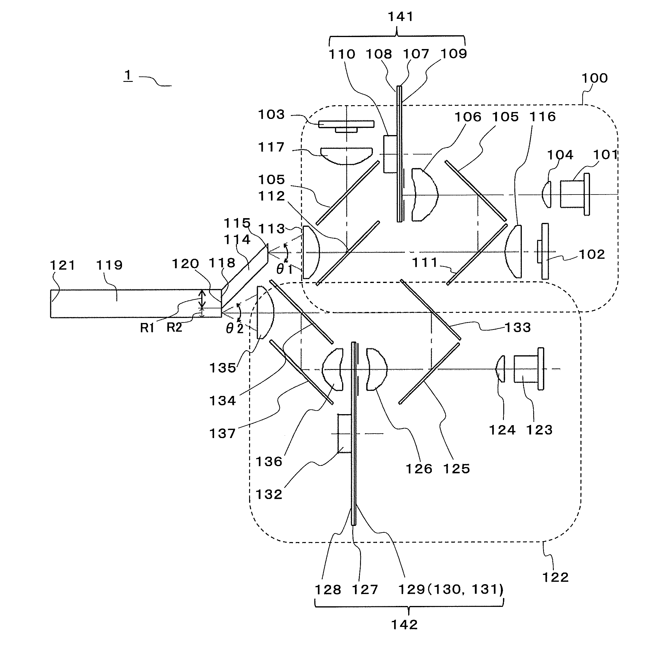
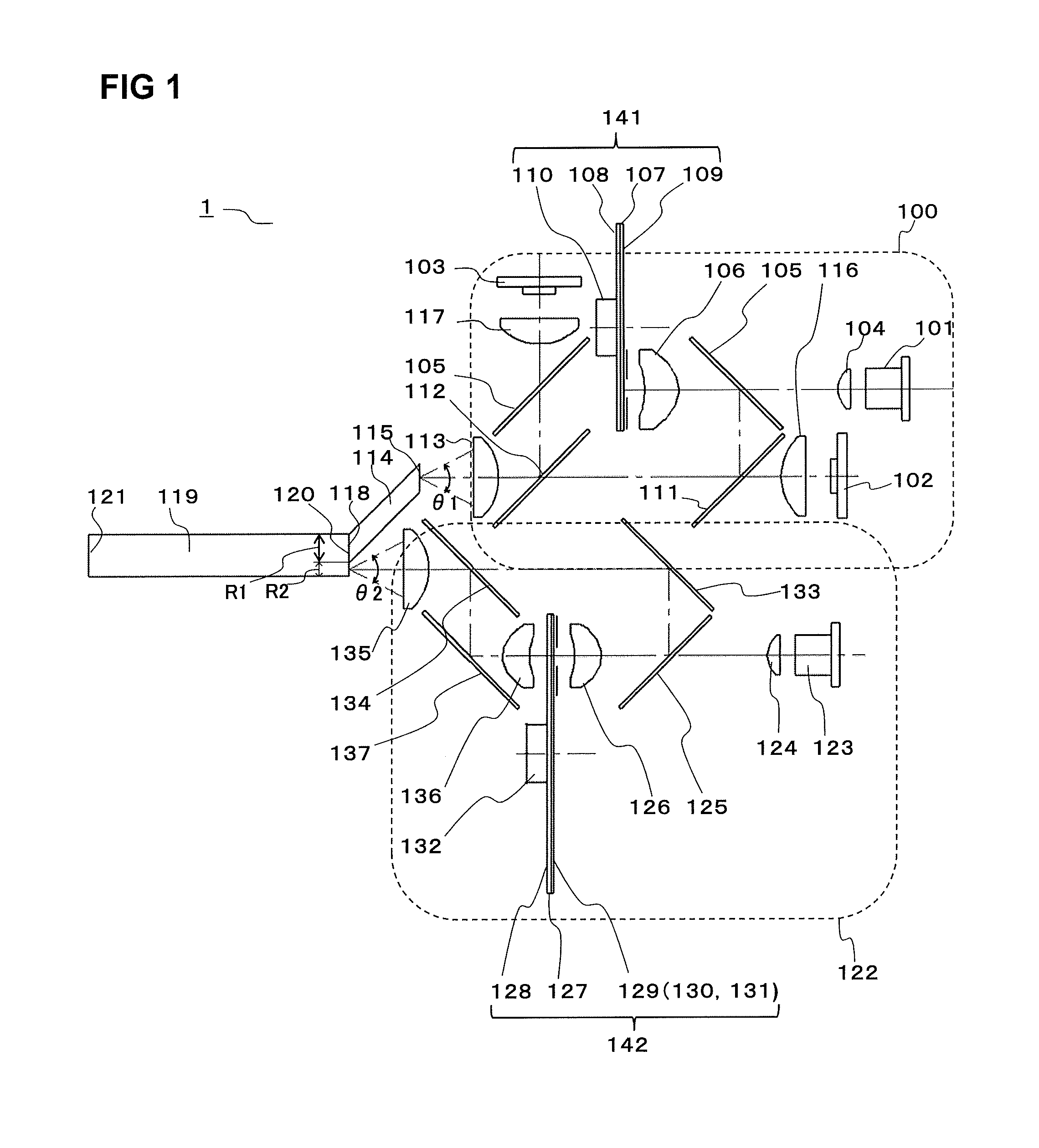
[0032]FIG. 1 is a configuration diagram of a lighting device according to a first embodiment.

[0033]The lighting device 1 combines lights emitted from a plurality of light sources and performs uniform illumination with a high brightness. The lighting device 1 includes a first light source section 100, a second light source section 122, a first rod integrator 114, and a second rod integrator 119.

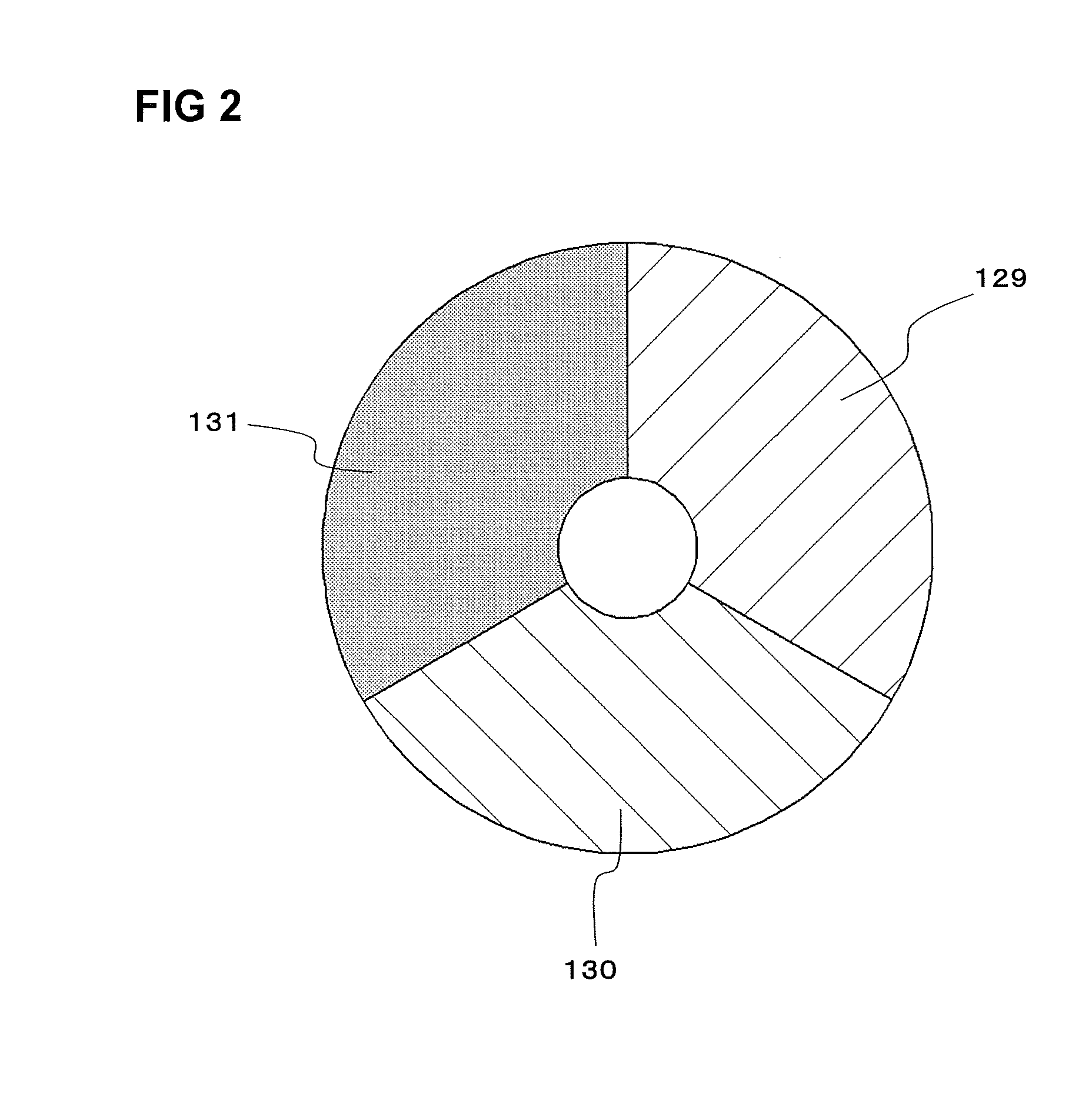
[0034]The first light source section 100 includes a laser element 101 emitting blue light, an LED 102 emitting green light, an LED 103 emitting blue light, collimator lenses 104, 106, and 116, red reflection dichroic mirrors 105 and 111, a blue reflection dichroic mirror 112, a rotation plate 141, a motor 110 rotating the rotation plate 141, and a converging lens 113. The rotation plate 141 includes: a disc-shaped base plate 108 formed from glass; a blue transmission dichroic mirror coat 107 applied to one surface of the base plate 108 (a surface thereof on the side opposite to the second rod ...

second embodiment

[0053]FIG. 4 is a configuration diagram of a lighting device according to a second embodiment.

[0054]The lighting device 2 according to the second embodiment is different from the lighting device 1 according to the first embodiment in the configurations of the light source sections.

[0055]A first light source section 200 is the same as the second light source section 122 of the first embodiment, but light converged by the converging lens 135 is converged on an incident surface 202 of a first rod integrator 201.

[0056]A second light source section 207 includes an LED 208 emitting green light, an LED 213 emitting blue light, an LED 215 emitting red light, collimator lenses 209, 214, and 216, a blue reflection dichroic mirror 210, a red reflection dichroic mirror 211, and a converging lens 212.

[0057]The green light emitted from the LED 208 is converted into substantially parallel light by the collimator lens 209 of which a focal point is located on a light-emitting surface of the LED 208....

third embodiment

[0059]FIG. 5 is a configuration diagram of a lighting device according to a third embodiment.

[0060]The lighting device 3 according to the third embodiment includes a pair of first rod integrators 301 and 317, a second rod integrator 304, a pair of first light source sections 300 and 316, and a second light source section 307.

[0061]Each of the first rod integrators 301 and 317 is the same as the first rod integrator 114 of the first embodiment. The first rod integrators 301 and 317 are disposed such that central axes thereof are inclined relative to an incident surface 319 of the second rod integrator 304, and so as to spread apart with increasing distance from the incident surface 319. Thus, a space is formed to the second light source section 307 side of first regions R1 and R1′ and a second region R2. By converging light emitted from the second light source section 307 within this space, an optical system can be disposed such that: the first light source section 300, the second li...


PUM


Abstract

A lighting device is provided which efficiently achieves a high brightness and a high image quality by using a solid light source which has long service life and does not need mercury. The lighting device includes a first light source section, a second light source section, a second rod integrator for combining lights emitted from the first and second light source sections, and a first rod integrator for guiding the light from the first light source section, to the second rod integrator. On an incident surface of the second rod integrator, a first region on which the light emitted from the first light source section is incident and a second region on which the light emitted from the second light source section is incident do not overlap each other, and the surface area of the first region and the surface area of the second region are different from each other.

Description

CROSS-REFERENCE TO RELATED APPLICATION[0001]The disclosure of Japanese Patent Application No. 2010-071996, filed on Mar. 26, 2010, is incorporated herein by reference.BACKGROUND OF THE INVENTION[0002]1. Field of the Invention[0003]The present invention relates to lighting devices that efficiently combine a plurality of light sources and that combine lights from different types of light sources, thereby allowing an image quality to be improved. Further, the present invention relates to projection type image display apparatuses using the lighting devices.[0004]2. Description of the Background Art[0005]In recent years, LEDs have been used as light sources for generic illumination, since they have long service life and high light-emission efficacy. The use of LEDs as light sources for projection type image display apparatuses is under consideration, since, for example, LEDs have long service life, do not include mercury, and do not rupture. However, LEDs have a broad light-emitting surf...

Claims


Application Information

Patent Timeline
IPC IPC(8): H04N5/74F21V9/16F21V5/00F21V7/00
CPCG03B21/14G03B21/204G03B33/06H04N9/3197H04N9/3111H04N9/3164G03B33/12G03B21/2013G03B21/2033
Inventor YAMAGISHI, SHIGEKAZUKITANO, HIROSHIFUSHIMI, YOSHIMASATANAKA, TAKAAKI
Owner PANASONIC CORP
Why Eureka
Try Eureka