Multi-Pole Optical Signal Switch

a multi-pole optical signal and switch technology, applied in multiplex communication, optical elements, instruments, etc., can solve the problems of unused beam steering and light of a specific wavelength blockag

Active Publication Date: 2011-09-29
II VI DELAWARE INC
View PDF10 Cites 26 Cited by
  • Summary
  • Abstract
  • Description
  • Claims
  • Application Information

AI Technical Summary

Benefits of technology

[0038]Further embodiments of the present invention provide an optical switch having multiple input and output ports, that can direct any number of WDM signals, each arriving at a respective input port, to any one of the output ports. According to such embodiments of the present invention, when an output for a WDM signal is switched from a first port to a second port, the switching can be performed in a hitless manner.
[0039]An optical device, according to an embodiment of the present invention, includes multiple ports for transmitting WDM signals therethrough, an array of LC pixels, each positioned to receive a WDM signal transmitted through one of the ports, and an array of reflective elements, each associated with one of the LC pixels. The LC pixels are controlled to cause a WDM signal incident thereon to attain an attenuation state while an output of the WDM signal is being switched by an associated reflective element. A control unit may be provided for controlling the LC pixels and the reflective elements and to synchronize the timing of

Problems solved by technology

Additionally, the light of a specific wavelength can

Method used


Image

  • Multi-Pole Optical Signal Switch
  • Multi-Pole Optical Signal Switch
  • Multi-Pole Optical Signal Switch

Examples


Embodiment Construction

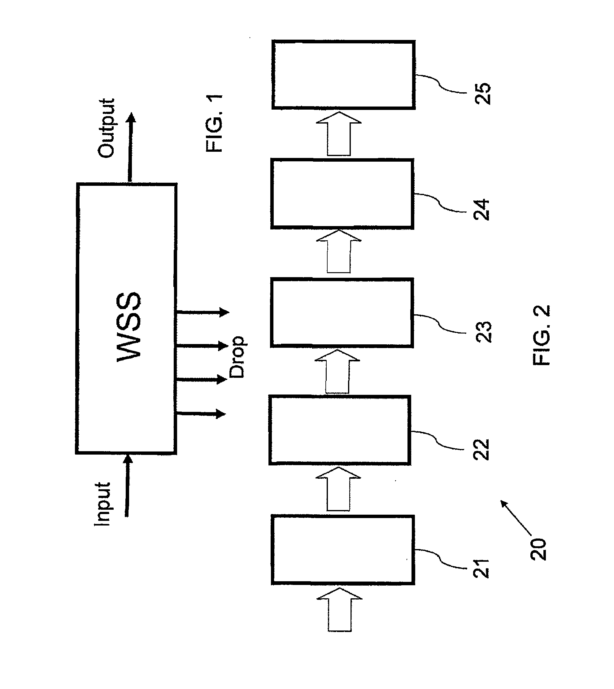
[0064]Reference is now made to FIG. 1, which illustrates schematically a block diagram of the functionality of an optical wavelength router, including a single input port, a single main output port and a number of Drop ports. The function of the router is to either transmit, to block or to attenuate any wavelength channel in the input signal, and to direct that signal, if transmitted or attenuated, to any of the output or Drop ports.

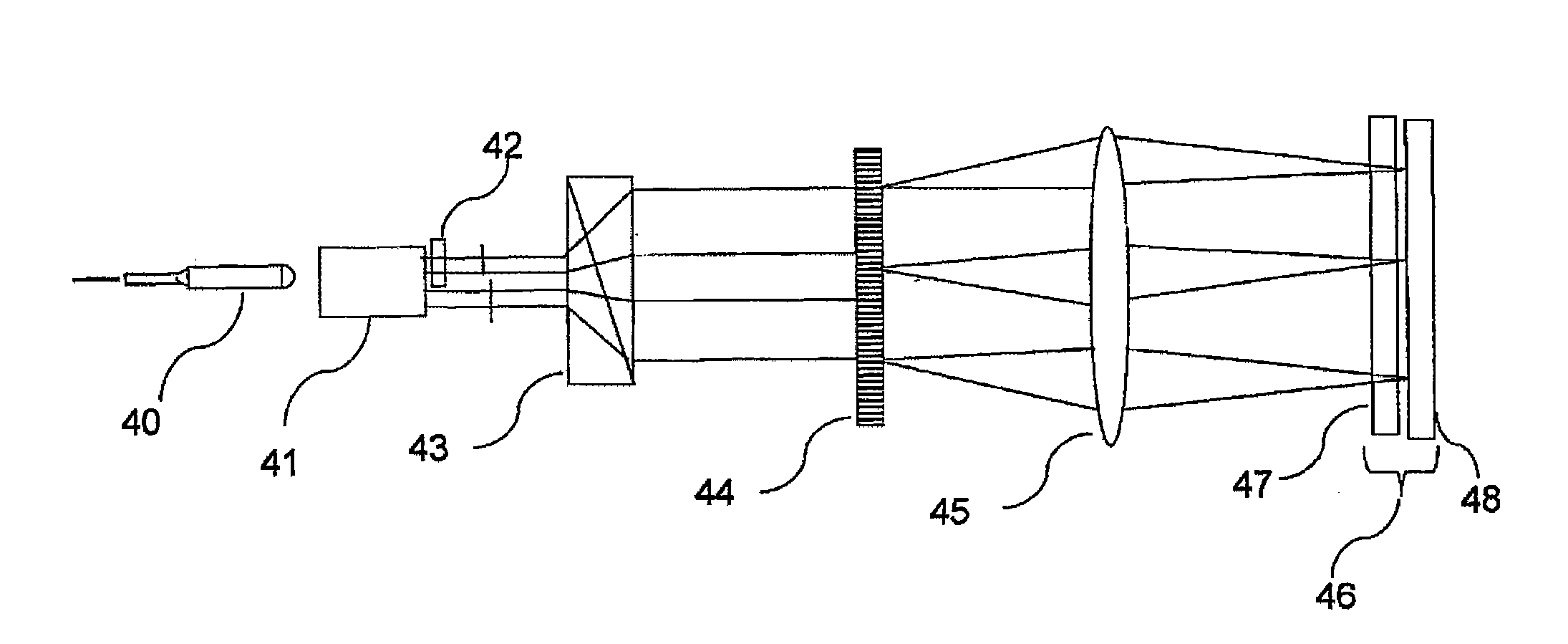
[0065]Reference is now made to FIG. 2, which illustrates schematically the router 20 of FIG. 1, as implemented according to a preferred embodiment of the present invention, in the form of a block diagram of the functionality of the separate operative parts of the router. The signals are input to the router through a Fiber Interface Block 21, which accepts the input signals and converts them into free-space beams for polarization processing, lateral expansion and spatial manipulation. According to a preferred embodiment of the present invention, the free-...


PUM


Abstract

An optical switch having multiple input and output ports directs any number of WDM signals, each arriving at a respective input port, to any one of the output ports. The optical switch includes an array of LC pixels, each positioned to receive a WDM signal transmitted through one of the ports, and an array of reflective elements, each associated with one of the LC pixels. The LC pixels are controlled to cause a WDM signal incident thereon to attain an attenuation state while an output of the WDM signal is being switched by an associated reflective element, such that when an output for a WDM signal is switched from a first port to a second port, the switching can be performed in a hitless manner.

Description

CROSS-REFERENCE TO RELATED APPLICATION(S)[0001]This application is a continuation-in-part of U.S. patent application Ser. No. 12 / 911,661, filed Oct. 25, 2010, which is a continuation of U.S. patent application Ser. No. 12 / 066,249, filed Sep. 3, 2008, now U.S. Pat. No. 7,822,303, which is a national stage application of PCT Application No. PCT / IL2006 / 001052, filed Sep. 10, 2006, which claims the benefit of U.S. Provisional Patent Application Ser. No. 60 / 715,695, filed Sep. 8, 2005.BACKGROUND OF THE INVENTION[0002]1. Field of the Invention[0003]One or more embodiments of the present invention relate to the field of optical communication networks and in particular to an optical router for directing any input optical signal arriving at any one or more input ports in a network node to one or more output ports.[0004]2. Description of the Related Art[0005]It is known in the field of optical communications to use optical wavelengths as optical carriers for carrying digital or analog informa...

Claims


Application Information

Patent Timeline
IPC IPC(8): G02F1/1335
CPCG02B6/2713H04Q2011/0035G02B6/29313G02B6/29383G02B6/3512G02B6/3548G02B6/356G02B6/3594H04J14/0204H04J14/0205H04J14/0212H04J14/0219H04Q11/0005H04Q2011/003G02B6/29311G02B6/3518
Inventor COHEN, GIL
Owner II VI DELAWARE INC
Why Eureka
Try Eureka