Motion detection apparatus and method

Inactive Publication Date: 2011-09-29
FUJIFILM CORP
View PDF7 Cites 7 Cited by
  • Summary
  • Abstract
  • Description
  • Claims
  • Application Information

AI Technical Summary

Benefits of technology

[0006]An object of the present invention is to suppress f

Problems solved by technology

However, with an image obtained by a non-stationary camera,

Method used


Image

  • Motion detection apparatus and method
  • Motion detection apparatus and method
  • Motion detection apparatus and method

Examples


second embodiment

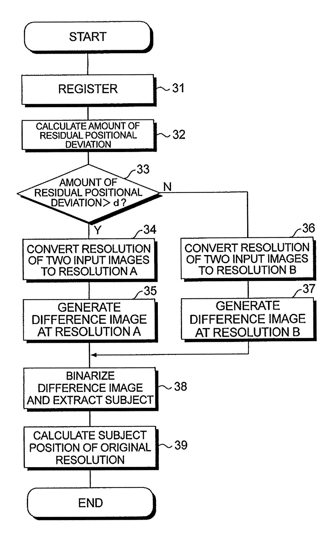
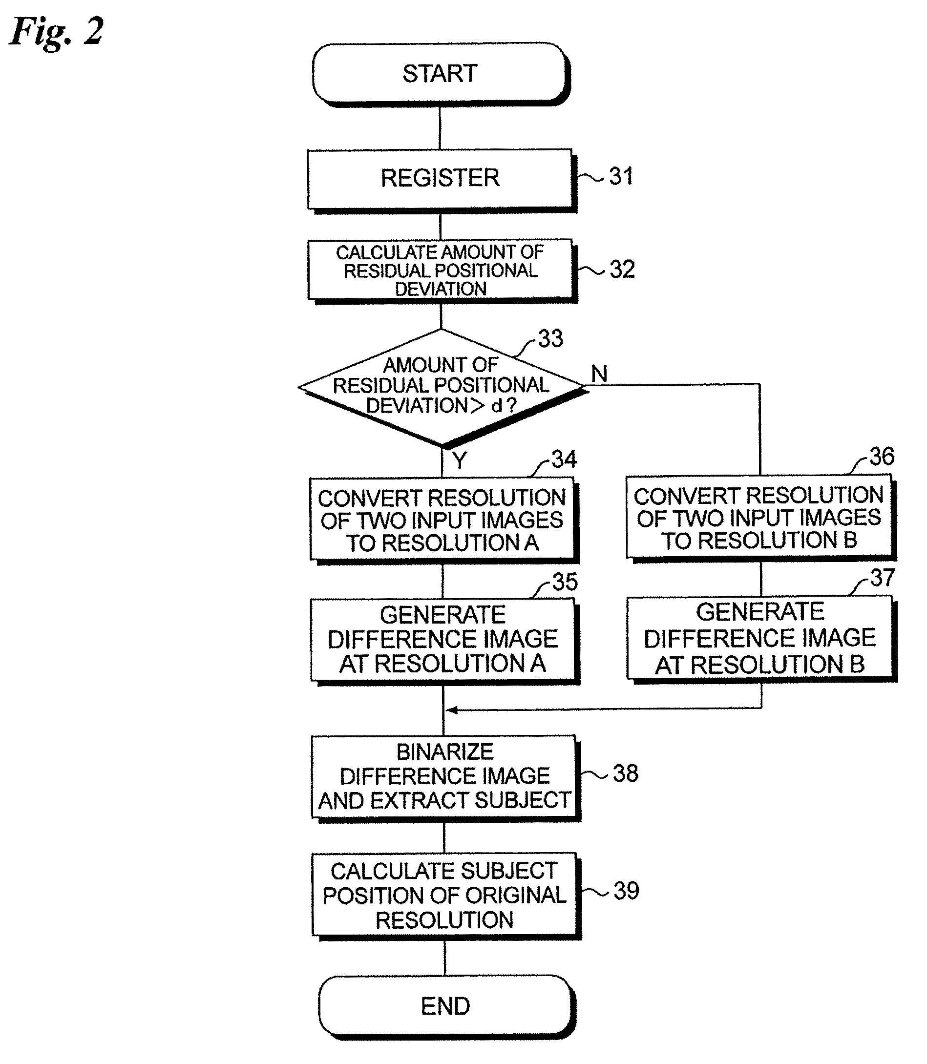
[0060]FIG. 5 is a flowchart illustrating motion detection processing according to a second embodiment of the present invention. This flowchart differs from the flowchart of the first embodiment shown in FIG. 2 in that with regard to the input images 81 and 82, low-resolution images 81A, 82A of resolution A, low-resolution images 81B, 82B of resolution B are created beforehand, and a difference image of resolution A calculated from the low-resolution images 81A, 82A and a difference image of resolution B calculated from the low-resolution images 81B, 82B are created (steps 41, 42). The difference image of resolution A and the difference image of resolution B are stored temporarily in the main memory 20.

[0061]If the amount of residual positional deviation is greater than the threshold value d, then the difference image of resolution A created beforehand is selected (read out of the main memory 20) (“YES” at step 33; step 43) and the subject (moving body) is extracted from the differen...

third embodiment

[0063]FIG. 6 is a flowchart illustrating motion detection processing according to a third embodiment, and FIG. 7 illustrates motion detection processing of the third embodiment in the form of images.

[0064]Motion detection processing according to the third embodiment differs from the processing of the first and second embodiments in that the input images 81, 82 are divided into a plurality of areas and a difference image is created for every divided area. Processing steps in FIG. 6 identical with those of the flowchart (FIG. 2) of motion detection processing of the first embodiment are designated by like step numbers and need not be described again.

[0065]FIG. 8, which corresponds to FIG. 4, illustrates, by the directions and lengths of arrows, the sizes and directions of amounts of residual positional deviation at a plurality of corresponding points in a fusion image 80 obtained by superimposing the two input images 81 and 82 after the registration thereof. FIG. 8 illustrates an exam...

fourth embodiment

[0072]FIG. 9 is a flowchart illustrating motion detection processing according to a fourth embodiment of the present invention. This flowchart differs from the flowchart of the third embodiment shown in FIG. 6 in that the binarization threshold value used in creating the binarized difference images used in detecting the subject (moving body) differs between a value applied to the difference image created using resolution A and a value applied to the difference image creating using the resolution B (steps 61, 62, 63). Processing steps in FIG. 9 identical with those of the flowchart of FIG. 6 are designated by like step numbers and need not be described again.

[0073]In subject (moving-body) detection processing, pixels (a region) having a difference value greater than that of a prescribed binarization threshold value in the difference image are detected (extracted) as pixels (a region) representing the subject (moving body). The smaller the binarization threshold value, the higher the ...


PUM


Abstract

Erroneous detection of a moving body in a background region is suppressed. Specifically, the position of one input image of two input images is made to coincide with the position of the other input image so as to eliminate relative positional deviation between the two input images. The amount of residual positional deviation in the thus registered two input images is calculated. The resolution of the two input images is lowered so as to take on a resolution A if the amount of residual positional deviation is greater than a prescribed threshold value d and take on a resolution B if the amount of residual positional deviation is equal to or less than the prescribed threshold value d (resolution A<resolution B). Binary difference image data is generated using the input images of lowered resolution and a motion region is detected from a binary difference image represented by the binary difference image data.

Description

BACKGROUND OF THE INVENTION[0001]1. Field of the Invention[0002]This invention relates to a motion detection apparatus and method.[0003]2. Description of the Related Art[0004]There are a variety of techniques for performing region detection using images, such as detecting a subject in an image (Japanese Patent Application Laid-Open No. 2007-122101) and finding a discrepancy (an altered portion) between two images (Japanese Patent Application Laid-Open No. 2008-269131).[0005]Processing for detecting motion (a moving body) in an image is available in the art. In motion detection processing, generally use is made of a difference in background or a difference between frames. In detection of a subject (moving body) using the difference between two images, it is required that the still regions (background regions) of the two images used in difference calculation be located at the same position. However, with an image obtained by a non-stationary camera, placing the still regions at the sa...

Claims


Application Information

Patent Timeline
IPC IPC(8): G06K9/00
CPCG06T7/2053G06T2207/20021G06T2207/20016G06T7/254
Inventor ENDO, HISASHIWADA, TETSU
Owner FUJIFILM CORP
Why Eureka
Try Eureka