Camera module

a technology of camera module and lens barrel, applied in the field of camera module, can solve the problems of high power consumption, complicated structure and manufacturing process, and large power consumption, and achieve the effects of reducing self-vibration, reducing power consumption and tilt phenomenon of lens barrel, and improving driving reliability

Inactive Publication Date: 2011-09-29
SAMSUNG ELECTRO MECHANICS CO LTD
View PDF25 Cites 84 Cited by
  • Summary
  • Abstract
  • Description
  • Claims
  • Application Information

AI Technical Summary

Benefits of technology

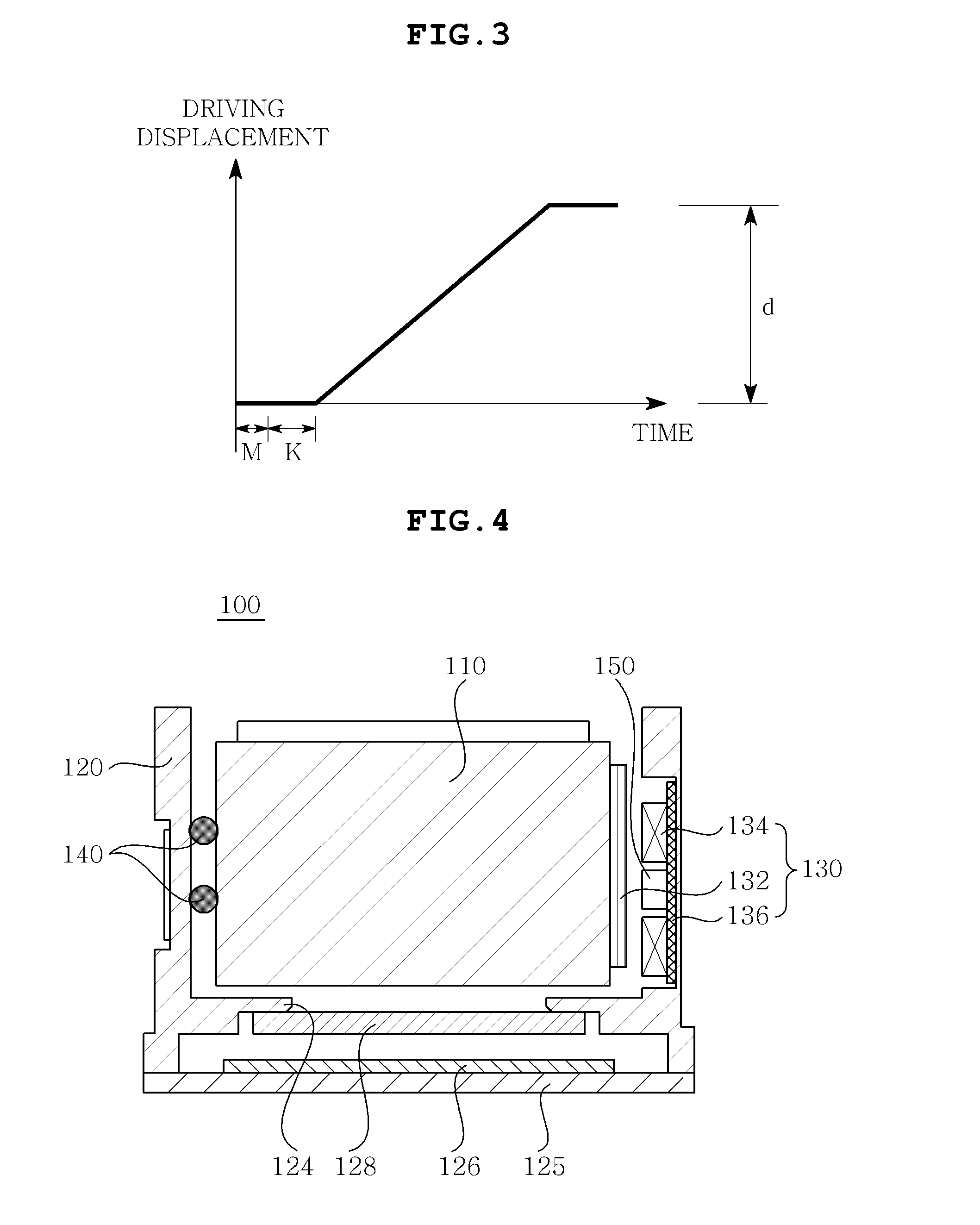
[0015]The present invention has been made in an effort to provide a camera module that can minimize power consumption and tilt phenomenon of a lens barrel and improve driving reliability by removing a preload part, and reduce self-vibration thereof at the time of driving the lens barrel by coupling damping members.

Problems solved by technology

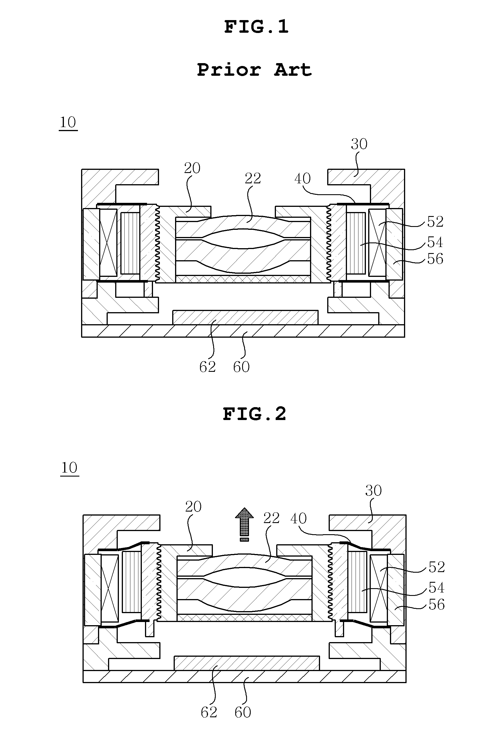
However, the camera module 10 according to the related art, using the driving principle described above, has a lot of power consumption due to the leaf spring 40 that restores the lens barrel 20 to the initial position.
That is, a large amount of current cannot but be applied to the coil 54 due to the preload K in order to drive the lens barrel 20, such that high power consumption occurs.
In addition, the leaf spring 40 makes the structure and manufacturing process complicated.
In addition, there is no structure for reducing shaking of the lens barrel 20 due to external impact or self-vibration thereof when driving the lens barrel 20 upward and downward, such that it is difficult to improve operational performance of the lens barrel.

Method used


Image

  • Camera module
  • Camera module
  • Camera module

Examples


Embodiment Construction

[0034]Various objects, advantages and features of the invention will become apparent from the following description of embodiments with reference to the accompanying drawings.

[0035]The terms and words used in the present specification and claims should not be interpreted as being limited to typical meanings or dictionary definitions, but should be interpreted as having meanings and concepts relevant to the technical scope of the present invention based on the rule according to which an inventor can appropriately define the concept of the term to describe most appropriately the best method he or she knows for carrying out the invention.

[0036]The above and other objects, features and advantages of the present invention will be more clearly understood from the following detailed description taken in conjunction with the accompanying drawings. In the specification, in adding reference numerals to components throughout the drawings, it is to be noted that like reference numerals designat...


PUM


Abstract

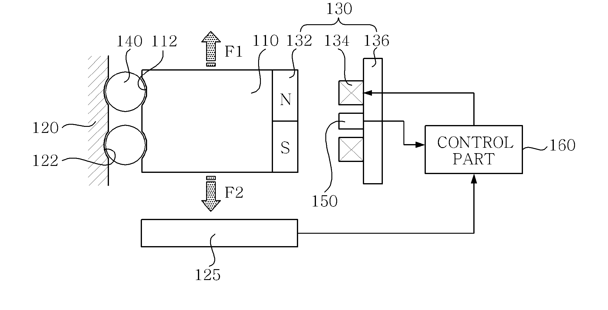
Disclosed herein is a camera module. The camera module includes: a lens barrel with a built-in lens collecting external images; a housing that has a receiving space in which the lens barrel is received; a driving part that is configured to include a magnet and a coil and provides a first driving force that drives the lens barrel upward and a second driving force that drives the lens barrel downward by an electromagnetic force that is generated from the magnet and the coil; a guide ball that is provided between the lens barrel and the housing and guides the motion of the lens barrel; and a position detection part that senses the position of the lens barrel, wherein the driving part drives the lens barrel upward and downward so that a preload part that provides preload returning the lens barrel to its initial position is not required.

Description

CROSS REFERENCE TO RELATED APPLICATION[0001]This application claims the benefit of Korean Patent Application No. 10-2010-0025848, filed on Mar. 23, 2010, entitled “Camera Module”, which is hereby incorporated by reference in its entirety into this application.BACKGROUND OF THE INVENTION[0002]1. Technical Field[0003]The present invention relates to a camera module.[0004]2. Description of the Related Art[0005]In general, electronic equipment or a personal portable terminal such as a cellular phone, a PDA, and the like is added with additional functions other than the main functions. Presently, a lot of electronic equipment that include a camera function have become popular among consumers. Therefore, a market for camera modules that are mounted in the electronic equipment have also expanded.[0006]According to recent market demands, a camera module has been correspondingly developed to gradually include additional functions such as autofocus, optical zoom, optical image stabilization (...

Claims


Application Information

Patent Timeline
Patent Type & Authority Applications(United States)
IPC IPC(8): G03B13/34
CPCG03B3/10H04N5/2254H04N5/2257G03B13/34H04N23/57H04N23/55G03B5/04G03B17/12G02B7/02G02B7/04G03B2205/0023G03B2205/0069
Inventor KANG, SEONG HOLEE, MYUNG JINBAIK, JAE HO
Owner SAMSUNG ELECTRO MECHANICS CO LTD
Why Eureka
Try Eureka